
Please read the general section first!
Purpose
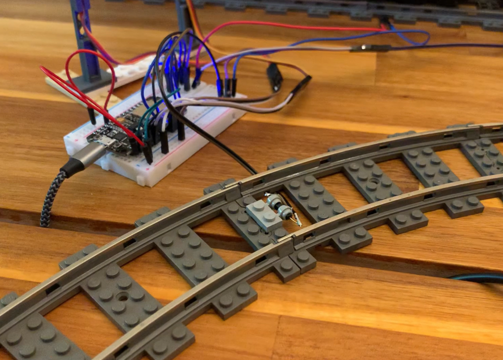
The MattzoLayoutController is designed to receive input signals from digital sensors like reed switches and pass the information on to the Rocrail via the MQTT broker.
Functional Description
The MattzoLayoutController connects to MQTT as described in the “General” section.
When a connected sensor has contact with a vehicle, the controller instantly sends a sensor event to the MQTT broker.
When a sensor looses contact for more than 0,1 seconds (configurable), the controller sends the “sensor disconnected” event to the MQTT broker.
Up to nine reed sensors (or other digital sensors) can be connected directly to the controller. With port extenders, even hundreds of sensors can be connected to the controller.
For more information about reed sensors refer to the sensor section.
Wiring
The following wiring diagrams shows two options to attach sensors to the controller.
The first diagram shows an example wiring of eight sensors and a status LED:
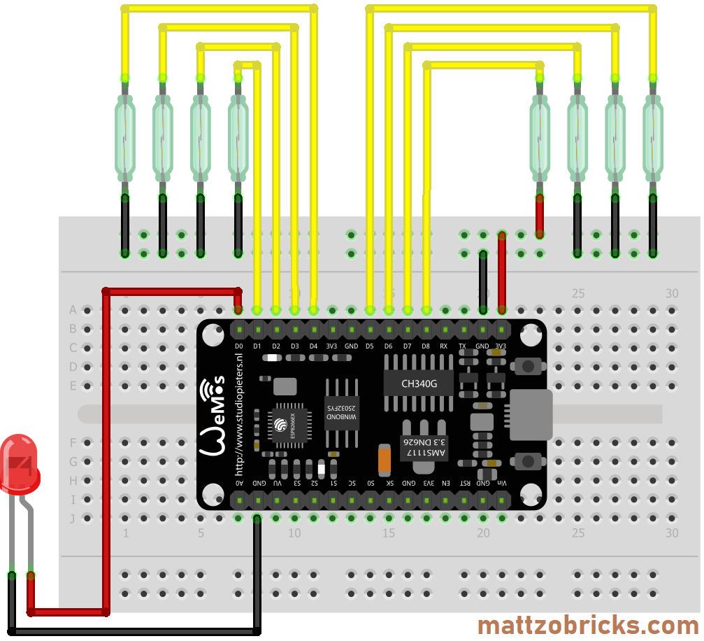
The status LED indicates to WiFi connection status, the MQTT connection status and lights up when one or more sensors are triggered. The status LED is very handy in practice. Therefore, this wiring option is recommended.
The next diagram displays the option of the MattzoSensorController with 9 sensors and no status LED.
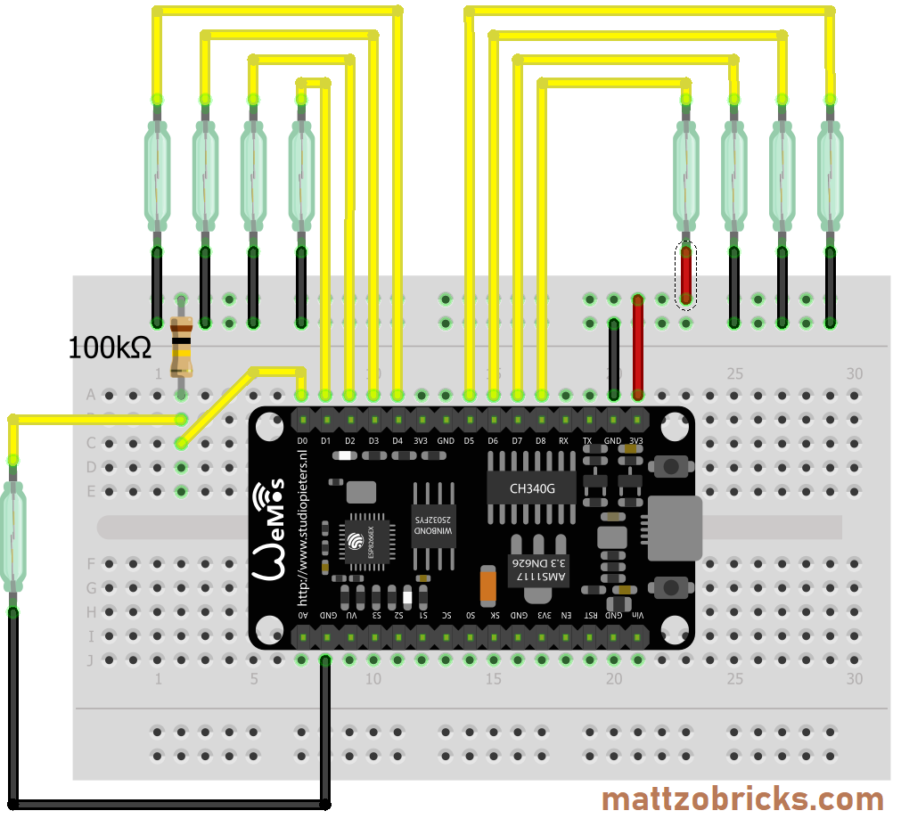
Instead of using pin D0 for the status LED, it is used for connection a ninth reed sensor. The option should only be used if you want to connect all of the nine connectible sensors to the controller. As the ESP-8266 has no internal pull-up resistors for pin D0, a strong resistor (10 or 100 kOhm) is required to pull up the port when the reed sensor is released. All other ports are pulled up internally by the MattzoController-Firmware.
Please note for both options, that the reed sensor on pin D8 must be connected to 3V3, not to GND on the other end. This is because D8 is actually pulled down, not pulled up.
One more thing: it is important to understand, that pins D3 and D4 must not be pulled down when you power the controller up, and that pin D8 must not be pulled up during boot. If you do that, the controller will not boot. That means, that the controller can not be successfully powered on when a train is on the sensors. The solution is easy: move the train a little bit away and reboot the controller. Or, even better, do not use D3, D4 and D8 for sensors if you don’t have to.
Required Components
- I/O board with micro controller. We have used a NodeMCU Amica Modul V2 ESP8266 ESP-12F. Similar modules should work as well.
- Up to 9 reed sensors (details: see sensor page).
- A pull-up resistor (10, 47 or 100 kΩ) for pin D0 (if sensor is installed on this pin).
- A LED (if status LED is installed). Make sure that the LED cope with the power supply. Depending on the type of LED, they each might need one additional resistor wired in series.
- Basic stuff like bread board, wires etc.
Power Supply
The controller can be powered up with a simple USB charger over USB or some other power supply of similar voltage that is connected to the VIN and GND pins of the controller.
Firmware Configuration
Please read the MLC general page first.
To configure the firmware configuration, you need to edit the controller configuration file (controller_config.h).
In this file, the following sections are relevant:
- SERVO WIRING CONFIGURATION
The section is clearly marked in the standard configuration file, and the different parameters are explained with code comments, so you shouldn’t have too many problems to understand what you need to do.
For a start, you should set the pinType to LOCAL_SENSOR_PIN_TYPE, as this is the setting for normal, local sensors. For an explanation of the other sensor types, please refer to the Sensors page.
Rocrail Setup
For general setup instructions please refer to the “General” section.
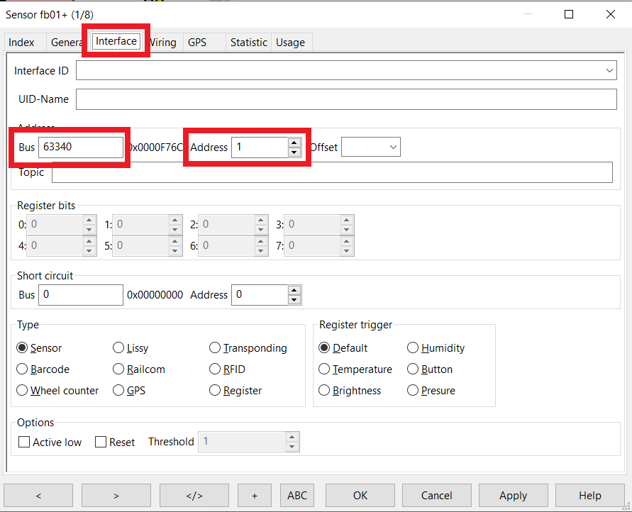
To setup the sensor in Rocrail, navigate to the interface tab of the sensor definition. The MattzoControllerID must be used as “Bus” parameter, and the port of the sensor as “Address”.
The first port has the number “1” (not “0”).
For using the sensor as a wheel counter see next section.
ALL OTHER INFORMATION ON THIS PAGE CAN BE NEGLECTED AND HAS NO MEANING!
Wheel Counting / free@enter
Rocrail has a very nice feature called “Wheel counter”. The idea is that the wheels (i.e. magnets) that pass a sensor are counted. By comparing the number of wheels that have passed the last sensor, Rocrail is able to notice that a train has completely passed a specific sensor on the layout. Rocrail is using that information particularly on “Enter”-Sensors of a block, and frees the block ahead after all “wheels” have passed the sensor. This speeds up train operations on your layout significantly, as the last block is available for other trains a lot earlier compared to waiting until a train has reached the “In”-Sensor of the subsequent block.
In order to use the feature, you need to configure the sensor type as “Wheel Counter” in the sensor configuration. The block and loco must also be configured as “free@enter”.
To use this feature safely, please make sure that not only your loco, but also the last waggon of your train has a magnet installed. Commuter trains need magnets in the front and in the end.
More details can be found in the Rocrail documentation.
Hi Mattze, I think something on this page is not quite right. The picture/wiring diagram for the MattzoSensorController on this page shows the wiring of the MattzoSignalController and not the diagram for the reed sensors.
I thought I should let you know, it’s just a small detail 🙂 keep up the great work!
Lucas, thanks for the heads up. Updated the page, should be correct now.
Yes, it is all good now!
Hi Mattze, you might eliminate the pull up resistors. Your ESP has those already built in:
// setup input for reed switches
for (byte i=0; i < sizeof(reed_pins); i++) {
pinMode(reed_pins[i], INPUT_PULLUP);
}
Thanks for the good work with the reed sensors!
Patricia,
thank you very much for this excellent idea. I have tested it, and it works indeed on ports D1 to D7. D8 is actually pulled down, if you configure it as pull-up. The problem with D8 is, that it must not be HIGH on start-up, or the controller will not boot.
I will integrate this into the next version of the firmware.
Warm regards and happy new year,
Mattze
              __/)

           .-(__(=:

        |\ |    \)

        \ ||

         \||

          \|

           |
Hello,
Locomotives are working great with the MattzoController so I moved to the MattzoSensorController.
1. Do I need to have the reed sensors connected to every Dx port (eg. for 2 sensors D1 and D2)
2. Do they have to be sequentially connected without any gaps in the sequence (eg. D1, D2 but not D1, D3)?
Does the “MattzoSensorController_Configuration.h” needs any customization like the MTC4PU?
Below is the errors I get from the failed compiler:
In file included from C:\Users\neeek\Google Drive\Lego\Trains\MattzoController\MattzoController_Sensor_Digital-1\MattzoController_Sensor_Digital-1.ino:11:0:
MattzoSensorController-1_Configuration.h:32:36: error: ‘D1’ was not declared in this scope
uint8_t SENSOR_PIN[NUM_SENSORS] = {D1, D2, D3, D4, D5, D6, D7, D8};
^
MattzoSensorController-1_Configuration.h:32:40: error: ‘D2’ was not declared in this scope
uint8_t SENSOR_PIN[NUM_SENSORS] = {D1, D2, D3, D4, D5, D6, D7, D8};
^
MattzoSensorController-1_Configuration.h:32:44: error: ‘D3’ was not declared in this scope
uint8_t SENSOR_PIN[NUM_SENSORS] = {D1, D2, D3, D4, D5, D6, D7, D8};
^
………………………………………
MattzoSensorController-1_Configuration.h:32:64: error: ‘D8’ was not declared in this scope
uint8_t SENSOR_PIN[NUM_SENSORS] = {D1, D2, D3, D4, D5, D6, D7, D8};
^
MattzoSensorController-1_Configuration.h:37:26: error: ‘D0’ was not declared in this scope
uint8_t STATUS_LED_PIN = D0;
^
C:\xxx\MattzoController\MattzoController_Sensor_Digital-1\MattzoController_Sensor_Digital-1.ino: In function ‘void setup()’:
MattzoController_Sensor_Digital-1:27:47: error: ‘D8’ was not declared in this scope
sensorTriggerState[i] = (SENSOR_PIN[i] == D8) ? HIGH : LOW;
^
exit status 1
‘D1’ was not declared in this scope
The above post can be removed!
I figure it out; I was using the wrong “Board”. Using “Generic ESP8266 Module” did not compile well, as can be seen from above. Then I switched to “NodeMCU 1.0 (ESP-12E Module) and Success!
As you probably can tell I am very green with Controlers. I am used to compile linux kernels and pkgs!
Very exciting project!
Thank you Mattze and comp.!
Hi Nikos,
thanks! I suggest to post your questions in the Forum, as I will deactivate the comments on the pages soon.
Cheers,
Mattze
Hi Matthew,
I will do that. Anyway, the above is just “white noise”and not much help for anyone. In the future I should give it some more time before posting!
Again, I would like to thank you and the other contributors for a GREAT and elegant project.
Cheers!
Nikos
hi danke dass du mir das mit den libs erklärt hast
als dank entwickle ich gerade ein baord konzept.
für deine software über I2C so kann man mehre platinen mit einenm master betreiben.
ich habe bereits eine test version für jedes deiner projekte am laufen werde sie noch erweitern und dann dir vorstellen.
hier mal den github link:
https://github.com/Backkevin/My_LEGO_Project
habe die seite gerade erst aufgesetzt , ich arbeite aber noch an allem
hier kann man die boards finden und nachbauen ,alles vor V2.1 sind noch im test
geänderte software findet man auch dort.