Prerequisites
Please read the general section first!
Purpose
The MattzoLayoutController is designed to receive signal commands from Rocrail via the MQTT broker and set light and form signals to a specific aspect.
Functional Description
When Rocrail requests a signal to change its aspect, it communicates this as a command via the MQTT broker. The MattzoController receives this command and evaluates, if the command is relevant for the specific controller (i.e. if the signal is connected to this controller).
Up to eight LEDs can be connected to the MattzoLayoutController if no port extenders are used. If standard two-aspect light signals with red and green LEDs only are used, four signals can be attached to one controller.
Wiring
The following diagram shows the wiring of the controller. As an example, four simple signals with one red and green LED each are connected to the controller.
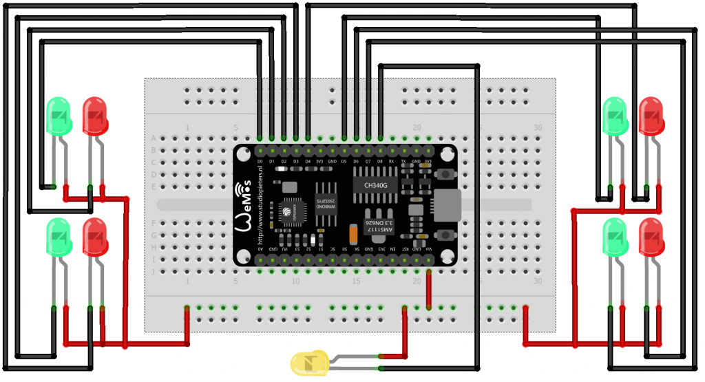
An additional LED can be connected to pin D8. The LED indicates the connection status of the controller to WiFi and MQTT.
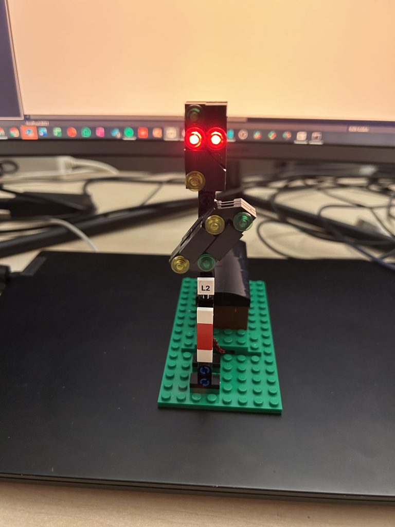
If you use Trixbrix signals, check out their special wiring. The middle wire (red) is the common plus terminal (anode) of the LEDs. It must be connected to 3V3 of the controller. The outer wires (black, yellow) are connected to pin D0-D7 of the controller and represent the minus terminal (cathode) of the two LEDs.
Required components:
- I/O board with micro controller. We have used a NodeMCU Amica Modul V2 ESP8266 ESP-12F. Similar modules should work as well.
- LEDs in different colors (red, green, for railway experts also possibly yellow and white) if you build the signals yourself.
- Possibly some resistors to protect the LEDs from burning off. Resistors with 220 Ω are frequently used for this job. In doubt ask the vendor of your signals or LEDs or check the specifications.
- Basic stuff like bread board, wires etc.
The controller can be powered up with a simple USB charger over USB or some other power supply of similar voltage that is connected to the VIN and GND pins of the controller.
Power Supply
The controller itself can be easily powered up via USB.
In the wiring diagram, the signals are connected to the 3.3V terminal of the controller. If this is too much for the LED that you are using, add a resistor in sequence to them.
The signals light up brighter if the plus terminal of the signals is connected to VIN (between 4.5 and 5V if supplied via USB) rather than to the 3.3V pin of the controller. We have tried this successfully with TrixBrix signals without breaking them. You are free to try it yourself, but you do this on your own responsibility.
In general, we recommend to check with the vendor of the signals or LED for what voltage the LED is built.
Firmware Configuration
Please read the MLC general page first.
To configure the firmware configuration, you need to edit the controller configuration file (controller_config.h).
In this file, the following sections are relevant:
- SERVO WIRING CONFIGURATION (relevant only if you use form signals),
- LED WIRING CONFIGURATION (relevant for light signals and form signals with lights), and
- SIGNAL CONFIGURATION.
The sections are clearly marked in the standard and configuration files. The parameters are explained in the definition of struct TSignalConfiguration in file MLC_types.h. Read it, and you shouldn’t have too many problems to understand what you need to do.
Some hints to the default and example configuration files:
- default configuration (MLC/conf/default/controller_config.h):
- Contains two light signals with 2 LEDs each.
- form signal example file (MLC/conf/examples/MLC_conf_FormSignals.h)
- Contains various main and distant semaphore signals with 2 or 3 aspects.
- complex light signals example file (MLC/conf/examples/MLC_conf_Complex_Light_Signals.h)
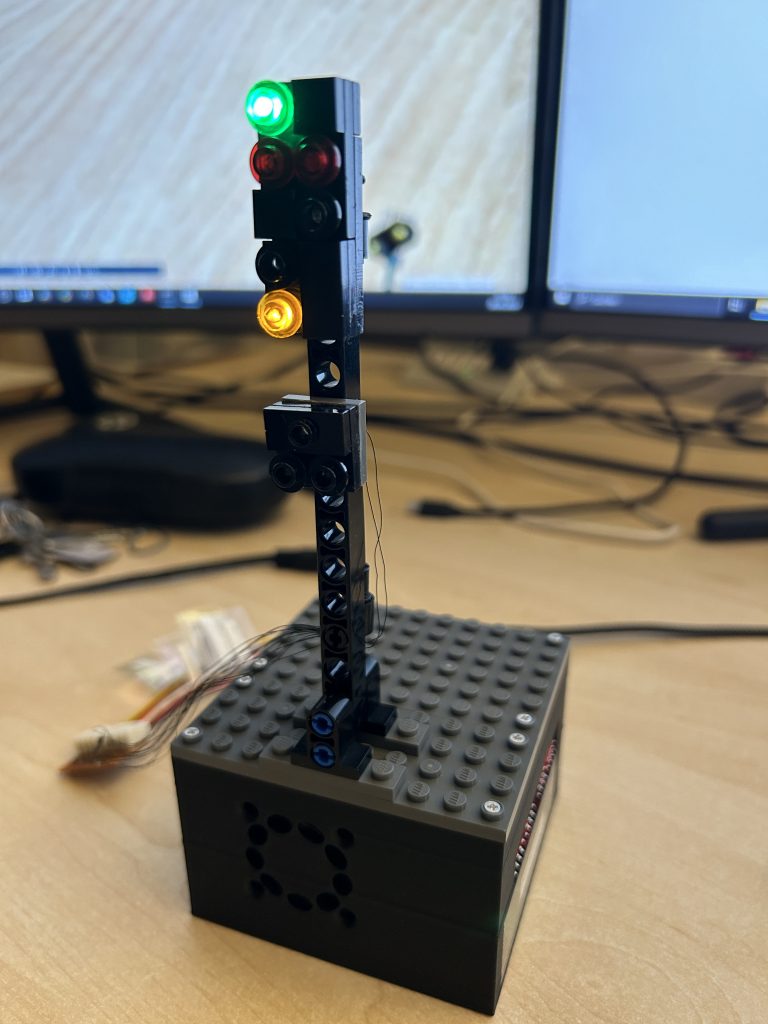
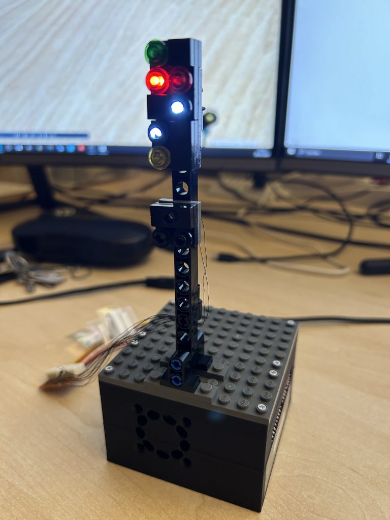
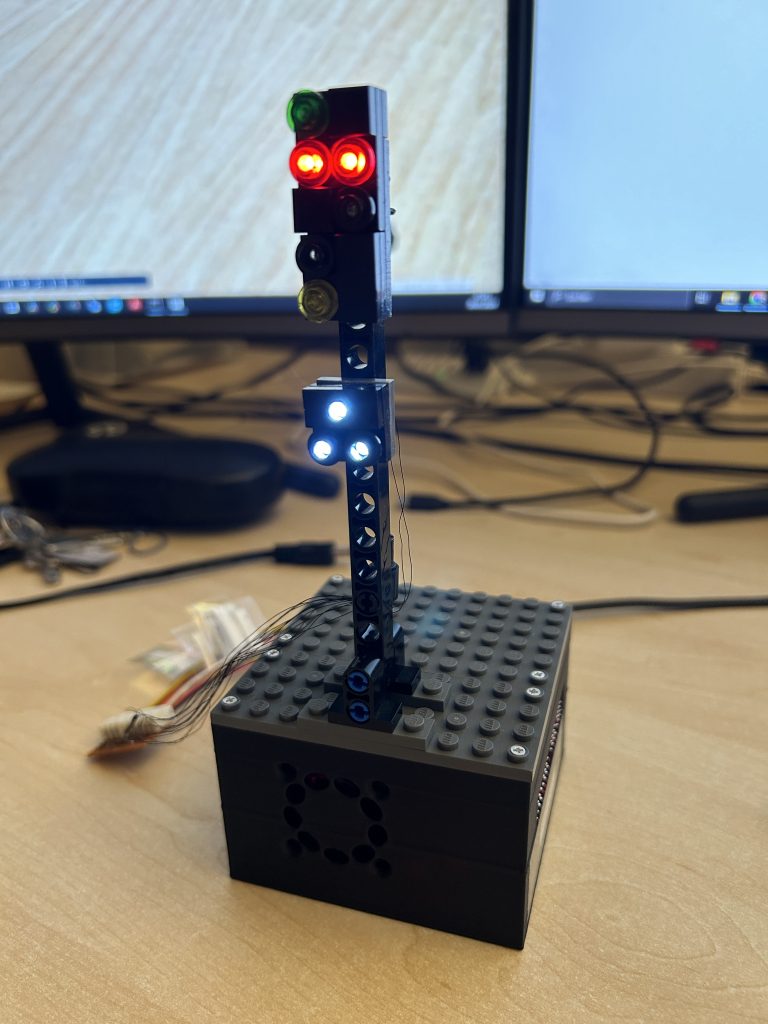
- Contains a complex main light signal with 6 LEDs and a complex distant signal with 5 LEDs, each with 6 aspects.
Standard signals
Most Mattzobricks users will use simple two-aspect-signals on their first layouts. That is perfectly fine.
More advanced users may try to build signals with 3 aspects one day. This is not very complicated in the MLC configuration, but it requires some configuration in Rocrail to handle the different aspects as desired, especially when using the auto router. You may even add a fourth aspect to a signal, usually a “white” aspect for shunting or similar.
Signals with up to 4 aspects are configured as follows:
- In Rocrail, select the control type “default” (see below).
- The signalRocrailPort parameter has no meaning.
- Enter distinct integer numbers (greater than 0) into the aspectRocrailPort array. The first signal in your MLC configuration receives 1 and 2 by convention. The second signal will receive 3 and 4 etc. Note that this is by convention only, you may define the port numbers freely.
Multi-aspect signals
Signals with more than 4 aspects require the control type “aspect numbers”.
Multi-aspect signals are supported from firmware release version 1.1 or higher.
Signals with more than 4 aspects are configured as follows:
- In Rocrail, select the control type “aspect numbers” (see below).
- Specifiy the signalRocrailPort in the MLC signal configuration. This may be any integer number greater than 0. Use 1 for the first signal by convention, 2 for the second etc.
- The aspectRocrailPort array is meaningless for these signals. You may fill it with “-1” values by convention.
Overshoot sensors
With firmware 1.0.2, overshoot sensors for signals were introduced.
The overshoot sensor is placed just behind the signal. When the signal is red, and the overshoot sensor is triggered, the emergency brake is triggered, and all trains stop automatically. The feature improves operational security on medium-sized and large layouts and helps to prevent chaos and consecutive mass crashes in case a train has overrun a red signal.
Overshoot sensors can be local and remote sensors.
Overshoot sensors only work for one-way tracks, because a using the track in reverse direction would always trigger the overshoot sensor.
Some good practices
- Take time and study the example files and see how the configuration works.
- Start with simple 2 aspect light signals.
- In, Rocrail the most relevant signal aspects are hardcoded. We recommend to use this order for your aspect definition in the signal configuration as well. The order is as follows:
- 1: red
- 2: green
- 3: yellow
- 4: white
Rocrail Setup – General
For general setup instructions please refer to the “General” section.
To setup the signal in Rocrail, navigate to the interface tab of the signal definition.
Two ways of controlling the signal via Rocrail are supported in the MLC.
Rocrail Setup – Control Type “Default”
This is the standard control default type. It works with signals with up to 4 aspects.
If in doubt, use this control type – especially if you are new to Rocrail!
To setup the signal in Rocrail, add a signal to your plan.
Then navigate to the Details page. Enter the following data:
- Signal type. Can be semaphore signal (form signal) or a light signal (there is no functional difference for the Signal type in Rocrail).
- Number of aspects. Enter a “2” for simple red/green signals.
- Signification. Select if the signal is a main signal or distant signal. If you don’t know what difference is, select “Main signal”.
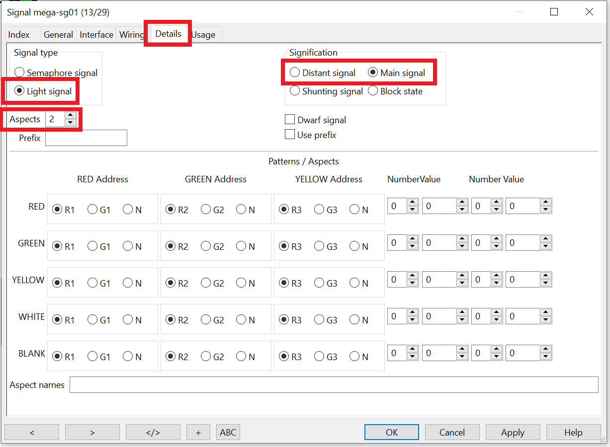
ALL OTHER INFORMATION ON THIS PAGE CAN BE NEGLECTED AND HAS NO MEANING!
Then navigate to the Interface tab.
Start with the Address/Port input boxes in the screen box “RED”. Enter the MattzoControllerID into the “Address” field. Enter the port number that corresponds with the “red” aspect in your MLC signal configuration into the Port field. If in doubt, enter “1”.
Continue with the screen box “GREEN”. Enter the MattzoControllerID again, and enter the port number for green from your MLC signal configuration. This is usually “2”.
If your signal has more than 2 aspects, continue with the “YELLOW” and “WHITE” accordingly (usually Port 3 and 4).
Make sure the option in frame “Control” is set to “Default”.
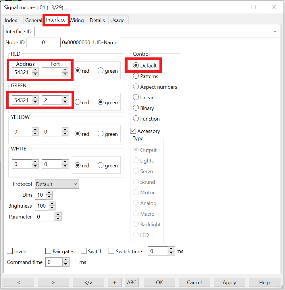
ALL OTHER INFORMATION ON THIS PAGE CAN BE NEGLECTED AND HAS NO MEANING!
Rocrail Setup – Control Type “Aspect numbers”
This section is for experts only. It is relevant only if you have signals with more than 4 aspects.
Multi-aspect signals – signal configuration
If you would like to operate a signal with more than 4 aspects, you need to use the Rocrail signal control type “aspect numbers”.
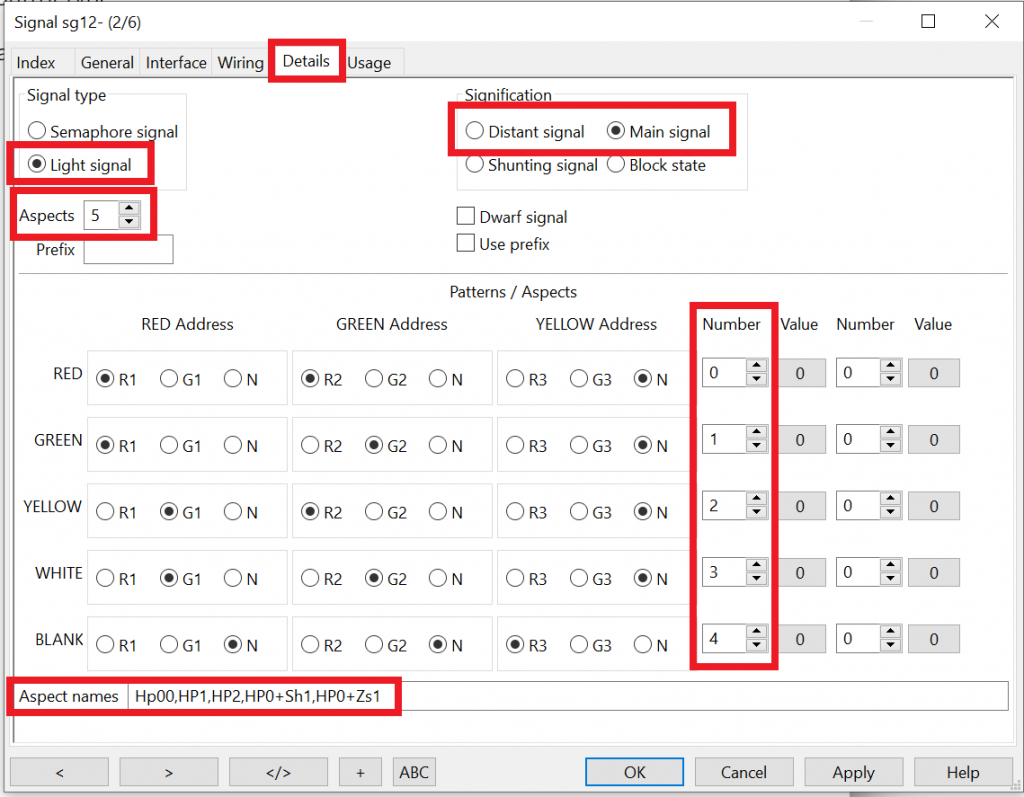
After you have created the signal in Rocrail, navigate to the Details page and enter the following data:
- The signal type (semaphore or light signal).
- The number of aspects (in the following example: 5).
- The signification (main or distant signal).
- Enter an integer number for each aspect. Just MUST start with 0 and count without interuptions upwards.
- Aspect names (they will show up in the context menu in Rocview) as a comma-separated list.
ALL OTHER INFORMATION ON THIS PAGE CAN BE NEGLECTED AND HAS NO MEANING!
Then navigate to the Interface tab. The MattzoControllerID must be entered as “Address” parameter, and the port of the LED as “Port”. This needs to be done only in the first input box combination.
In the “Control” frame, select “Aspect numbers”.
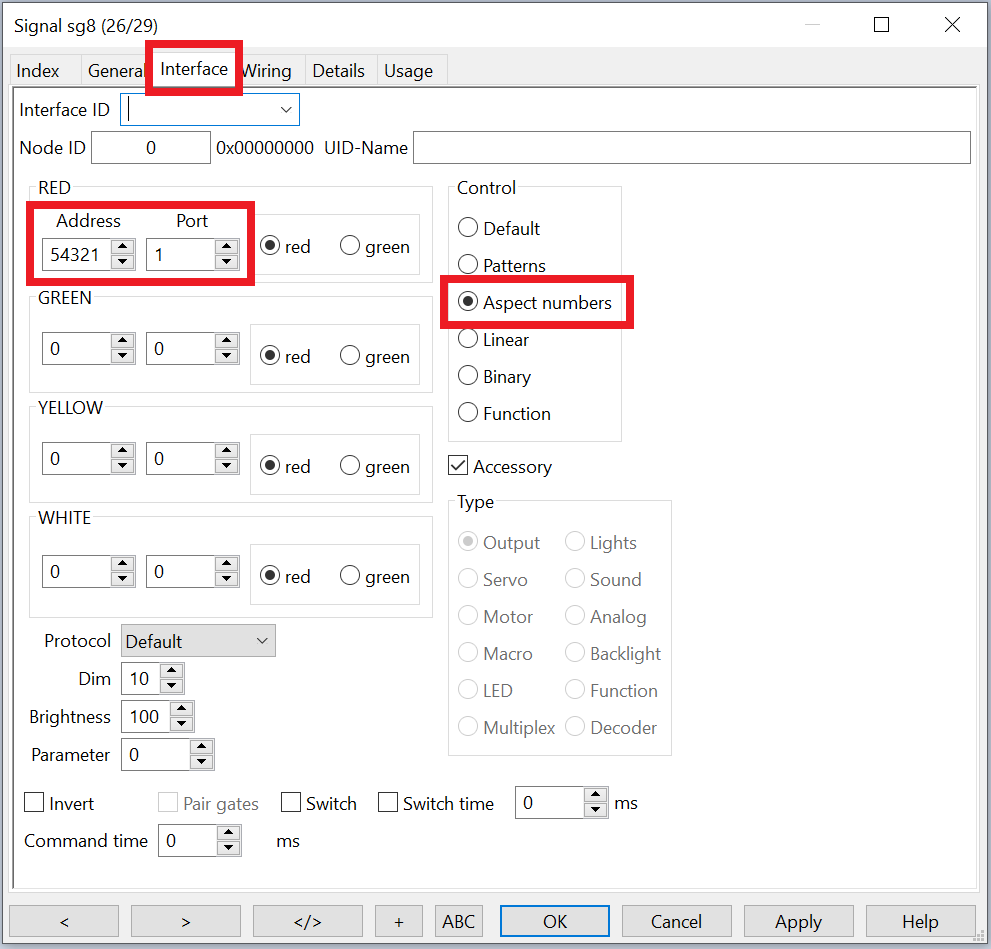
ALL OTHER INFORMATION ON THIS PAGE CAN BE NEGLECTED AND HAS NO MEANING!
Multi-aspect signals – route configuration
The auto-router and the routing automatic in Rocrail handles multi-aspect signals without problems – despite the Rocrail documentation that negates this fact. Just let the auto-router do its job, and do the usual route corrections for yellow and white aspects afterwards.
It gets complicated if you want to use one of the “higher” aspects of your signal (i.e. the 5th aspect and higher) in automatic routes. To enable this, you need to do two things:
- Disable the signal automatic for the route.
- Add the required signal commands manually to the route.
In Rocview, open the Route definition and navigate to the General tab.
In the “From signal pair” frame, select “None”. This deactivates the automatic signal management in Rocrail for this route.
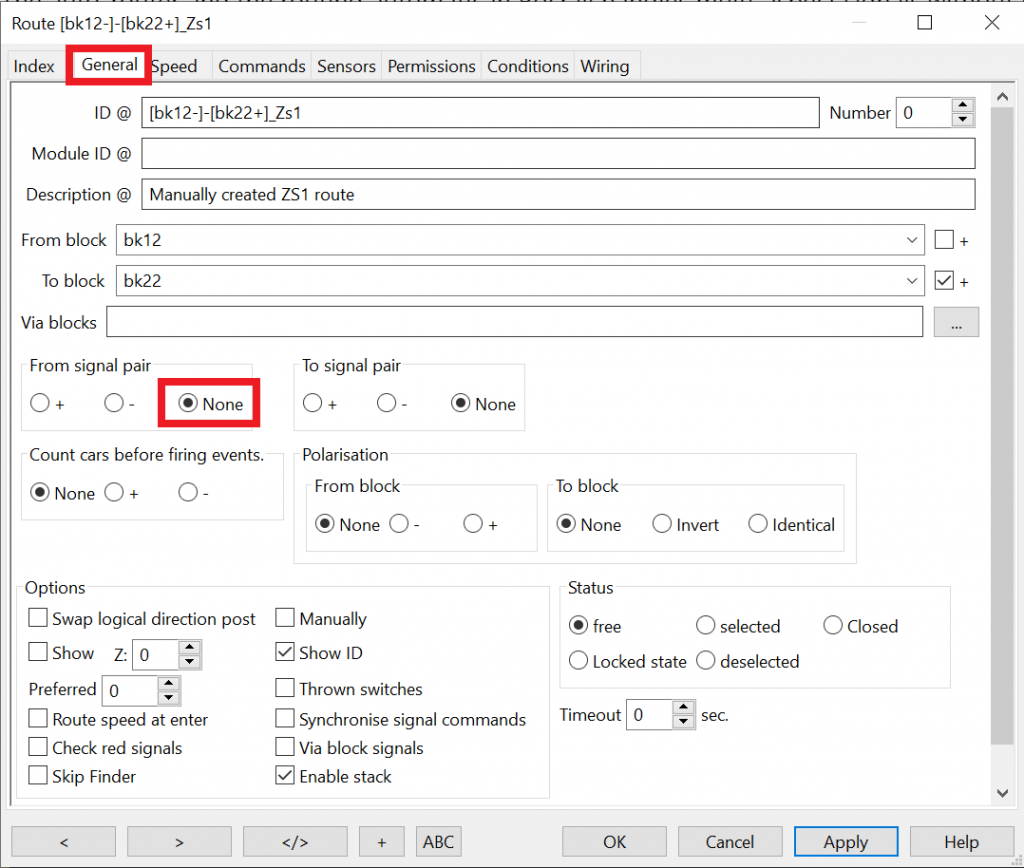
If you send a train via this route now, the outbound signal will do – just nothing! What you need is to add route commands to operate the signal.
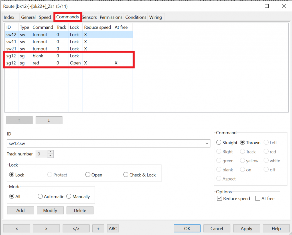
To do this, navigate to the Commands tab.
Enter one commands to set the signal to the desired aspect to let the train pass, and another command to send the signal back to red when the route is released.
As always, when you change automatically created routes, remember that it is a good idea to set the route to “manual” to protect it from subsequent changes from the auto-router.
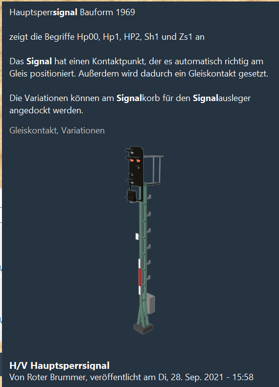
Multi-aspect signals with 3D Train Studio
If you the control type “aspect numbers” in Rocrail, and you simulate your layout in 3D train studio, make sure you use signal that can handle the required number of aspects (e.g. the “H/V Hauptsperrsignal” with the five aspects Hp00, Hp1, Hp2, Sh1 and Zs1).
Important: if you select “control type” aspect numbers in Rocrail, the signal must have more than 4 aspects, else it will not work correctly in 3D Train Studio.
For this reason, follow this simple rule to choose the control type that works both in Rocrail, your layout and 3D Train Studio:
- Up to 4 aspects: select control type “default”.
- More than 4 aspects: select control type “aspect numbers”.
There are multiple example configuration files for light signals that use control type “aspect numbers”.
Rocrail Setup – distant signals
Configuring and automating distant signals
There is no significant difference between configuring main and distant signals.
To always make the distant signal show the same aspect as the main signal, you need to configure the distant signal together with the main signal in the configuration for the block, tab “signals”. For each side of the block, you can define a pair of a main and a distant signal. The signals are then synchronised and set automatically by Rocrail when moving trains on the layout in auto mode.
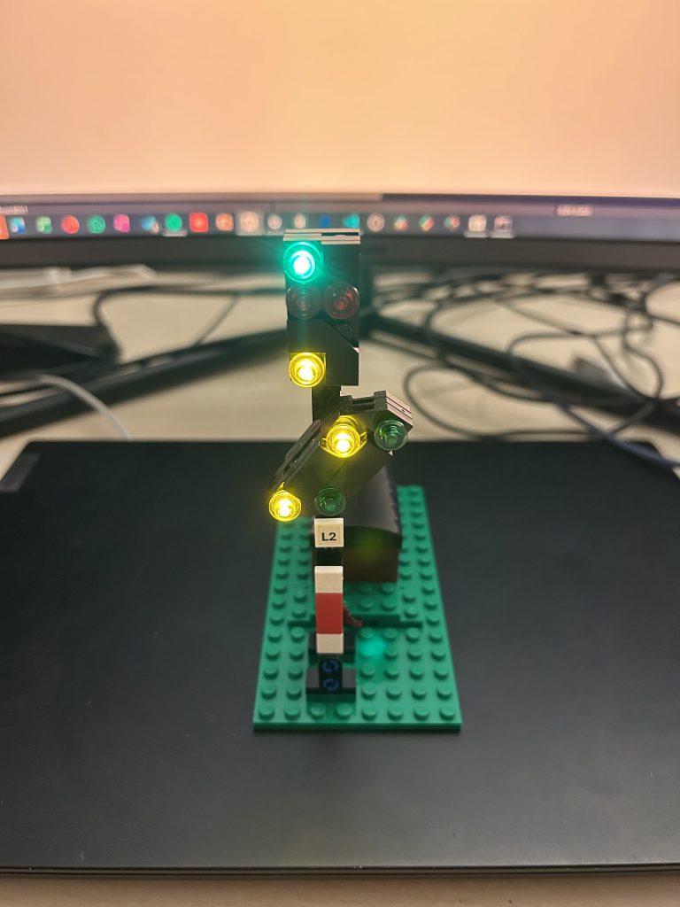
Blanking co-located light distant signals
Blanking co-located distant signals is a typical example of using multi aspect signals in Rocrail.
Here is the problem: if main and distant signals are co-located, the screen of the distant signal needs to show “blank” if the main signal shows “red”. The reason is, that any risk shall be avoided that a train engineer accidentially confuses the lights of a distant signal with the main signal screen, and passes the signal combination though the main signal commands “halt”. Additionally, a distant signal is meaningless while the main signal just ahead of the train is red, because the train needs to stop anyway.
Assuming that the main and distant signal both have three aspects, only seven combinations make sense:

But how do we set this up in Rocrail?
Follow these steps:
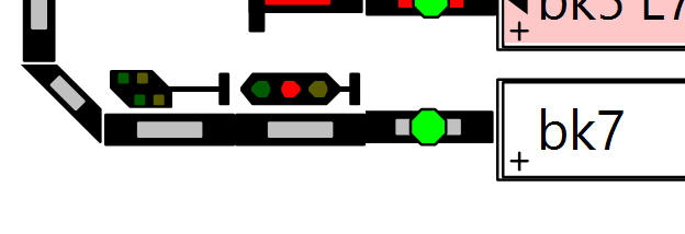
1. Add a main signal and a distant signal close to each other behind the block. That means that the signal combination is treated as two indepedent signals.
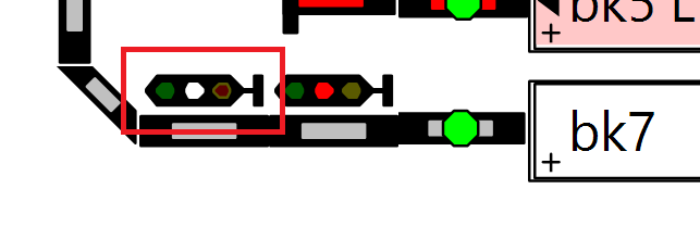
2. Increase the number of aspects of the distant signal to 5.
It sounds weird, but the reason is, that signals aspects are more or less hard-wired in Rocrail. The first four aspects are red, green, yellow and white. For distant signals, the fifth aspect is, as you may already have guessed, the “blank” aspect. We need precisely this aspect to blank the distant signal.
After you have increased the number of aspects, the distant signal looks a bit different:
3. Set the control type of the distant signal to “aspect numbers”.
Signals with more than 4 aspects require this control type.
4. Setup the main signal to blank the co-located distant signal on “red”.
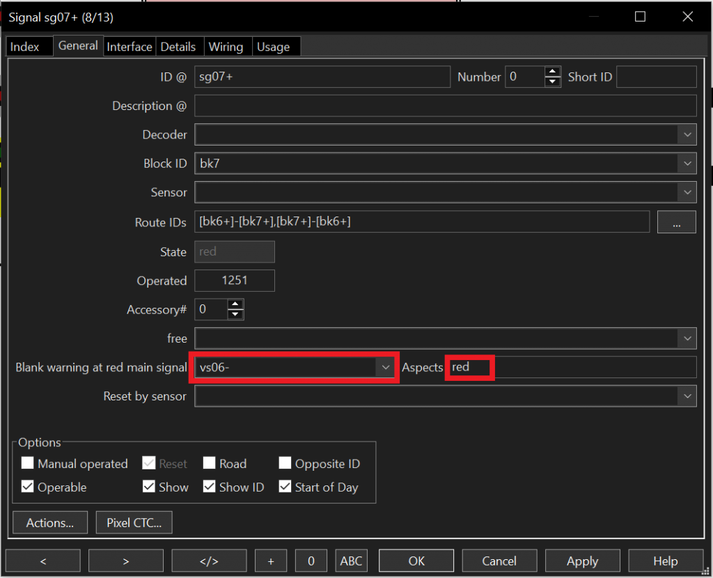
Navigate to the configuration dialog of the main signal. On the “General” tab, you’ll find two important fields:
- Blank warning at red main signal: select the co-located distant signal here.
- Aspects: select the “red” aspect of the main aspect. This is usually “red”, but it could also be “Hp00” or “Hp0”, if the main signal also uses control type “aspect numbers” and you have named the red aspect accordingly.
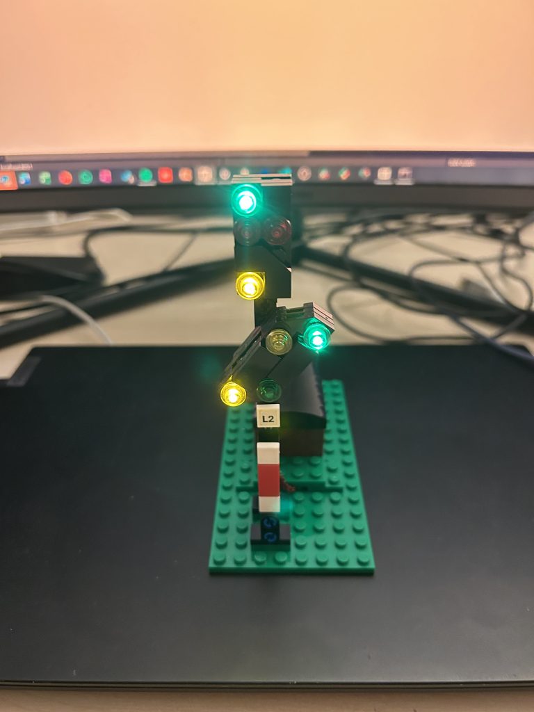
5. Test it
Set the main signal to different aspects. Upon “red”, the distant signal should now go to aspect number 4, which in Rocrail is usually indicated with single white light in the middle of the signal icon.
If you have configured the MLC firmware correctly, the distant signal screen should now show a blank screen.