
Please read the general section first!
Purpose
The MattzoTrainController for Power Functions (MTC4PF) acts as a controller for LEGO Power Function Train Motors (or compatible) or other Power Function motors, e.g. the XL motor for the Emerald Express.
The MTC4PF also switches train lights on and off.
The MTC4PF can control Power Functions motors directly, or it can relay the logical commands to “virtual” motor shields like the LEGO Infrared Receiver 8884 or 4DBrix WiFi Train Receivers (supported in older versions only). When using virutal motor shields, it can even control multiple trains at the same time.
Functional Description
When Rocrail wants to make a train go into a certain direction, it communicates this as a “loco” command via the MQTT broker.
The MTC4PF receives the loco command and checks, if the command is relevant for the controller by comparing the loco id of the Rocrail command with the loco id or loco ids stored in the controller. If the loco is controlled by the controller, the desired speed and direction are translated into the correct power setting for the LEGO train motor.
Up to two motors can be directly attached to the MTC4PF, one on each output of the motor shield. In the source code, you can configure the sense of rotation for both motors individually. A typical setup of two motors under a single train would usually be forward/reverse.
Please note that you must not connect more than one motor to a single output of the L9110 motor shield. Attaching two or more motor to a single output of the motor shield will overloaded it and eventually make it burn off.
Besides the directly connected motor shields, the MTC4PF can also act as a command relay module and pass the Rocrail commands on to trains with a LEGO Infrared Receiver 8884 on board. Both versions of the LEGO Infrared Receiver 8884 (v1 and v2) are compatible. It is possible to install the MTC4PF 1) somewhere on the layout, or 2) in the train. By installing it in the train close to the IR receiver, you can make sure that the train is always in contact with the IR LED on the controller. This enables routes through different rooms and through tunnels. Multiple trains with IR receiver can be controlled by a single MTC4PF. Trains can have more than IR receiver on board, which will be controlled synchronously by the MTC4PF. The turning direction of the individual motors can be set individually.
Older versions of the MTC4PF firmware can also relay Rocrail commands to 4DBrix WiFi Train Receivers. Multiple trains with 4DBrix WiFi Train Receivers can be controlled by a single MTC4PF. Trains can have more than 4DBrix WiFi Train Receiver on board, which will be controlled synchronously by the MTC4PF. The turning direction of the individual motors can be set individually.
You can also attach LED lights to the controller. They can be switches on and off with the function keys on the loco control panel in Rocrail. You may use all unused pins of the controller for extra lights. Rocrail supports up to 32 functions.
The controller continuously monitors its power supply. We plan to adapt the motor power to the decreasing voltage of the battery in future versions of the firmware.
Wiring
Wiring with L9110 motor shield
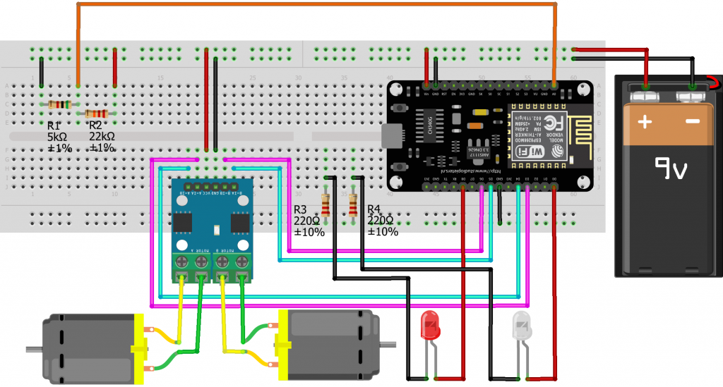
The following sketch shows the wiring of the controller with a directly attached motor shield L9110, 2 train motors and 2 LEDs:
Required components:
- I/O board with micro controller. We have used a NodeMCU Amica Modul V2 ESP8266 ESP-12F. Similar modules should work as well.
- Motor shield L9110
- 2 channel motor shield.
- Max. 12V.
- ~800mA maximum continuous current.
- 2A max. peak current (this is about the blocking current of a LEGO train motor).
- LEGO power functions cable, cut in two halfs.
- Power supply, around 9V. Some options are:
- Non-rechargeable batteries
- 6 AA or AAA batteries
- 9V block battery
- Rechargeable batteries
- 8 rechargeable AA or AAA batteries
- rechargeable 9V block battery
- If the loco provides enough space, we always try to use 8 rechargeable AA batteries.
- Non-rechargeable batteries
- Basic stuff like bread board, resistors, wires etc.
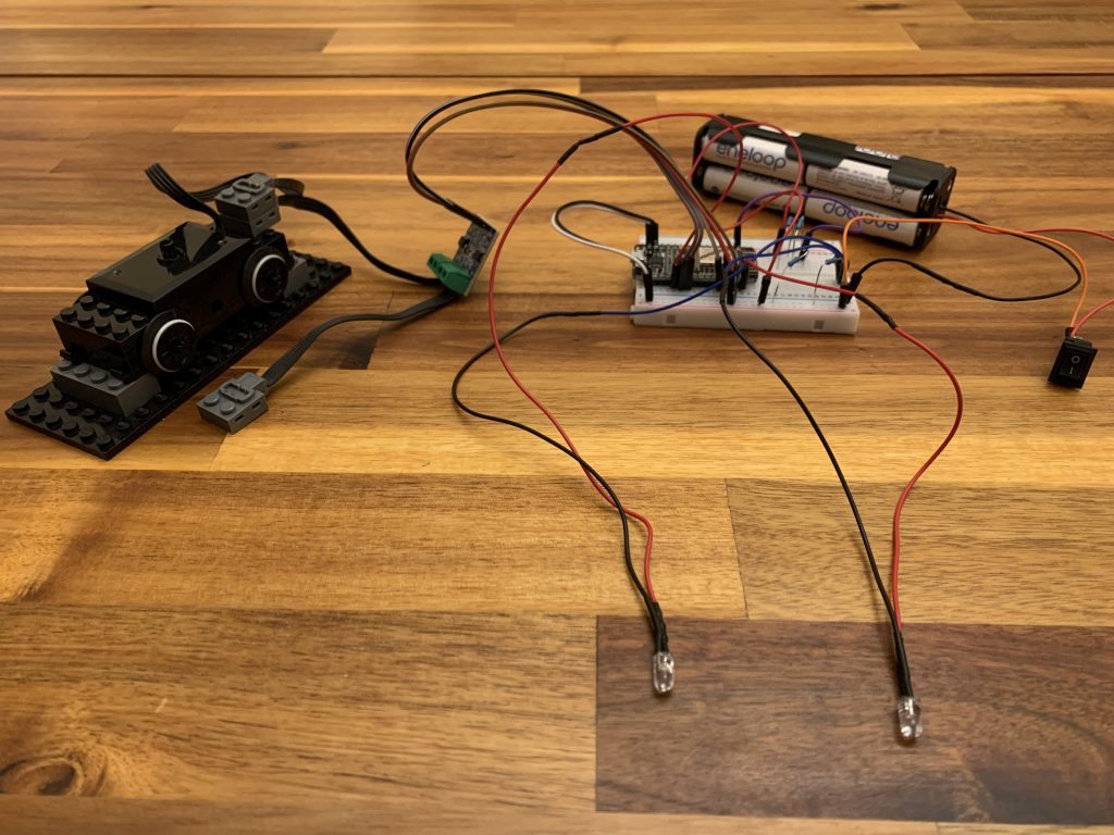
The following picture shows a MTC4PF with motorshield L9110 and the typically required components and cables:
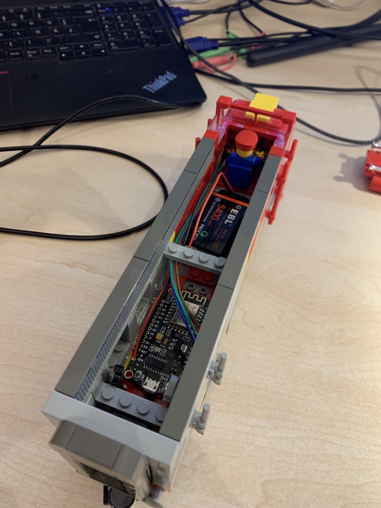
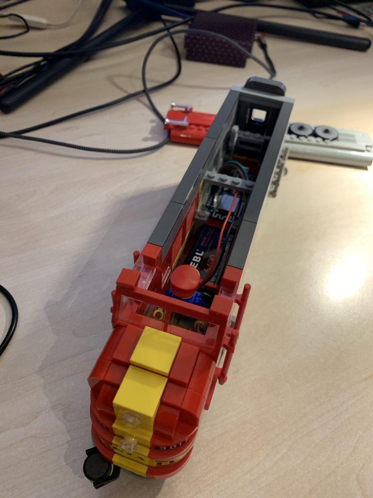
The following pictures show a Santa Fe locomotive with a MattzoTrainController for Power Functions:
Please be aware that LEGO Power Functions lights set no. 8870 require ALL FOUR PINS of the Power Functions plug to be wired correctly, i.e. the constant plus/minus terminals, and the switched plus/minus terminal. There are sufficient resources on the web that show the correct terminal mapping.
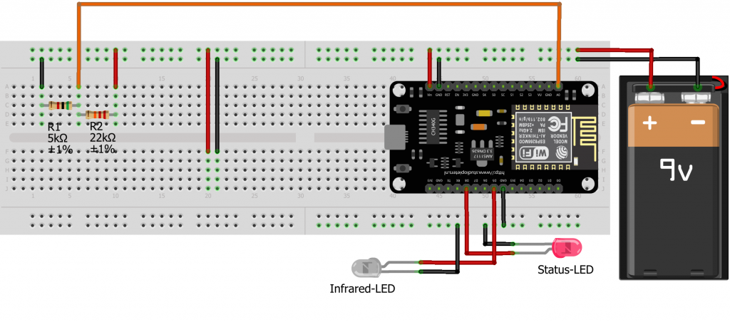
Wiring with infrared LED
The following sketch shows the wiring of the controller with an infrared LED and without a physical motor shield. The infrared LED is used to control a LEGO infrared receiver type 8884 (see section “Functional Description” above).
Required components:
- I/O board with micro controller. We have used a NodeMCU Amica Modul V2 ESP8266 ESP-12F. Similar modules should work as well.
- An infrared LED.
- Power supply, see above.
- Basic stuff like bread board, resistors, wires etc.
An infrared LED works the same way as any other LED. The only difference is that the emitted light is in the infrared spectrum and therefore invisible to the human eye. Connect it like any other LED, i.e. the long leg is connected to the plus terminal (the I/O port of the controller), and the short leg is connected to GND (ground = minus terminal).
In the wiring diagram and the example configuration in the firmware code we have chosen pin D5 for the anode of the infrared LED. This is handy because most ESP-8266 modules have a GND pin just next to D5. This enables you to solder the LED directly on the board.
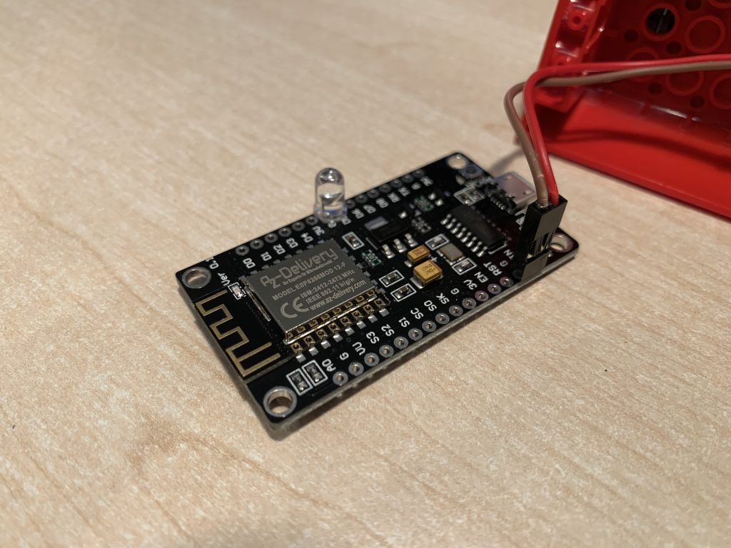
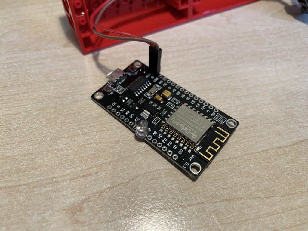
The following pictures shows a MTC4PF with the infrared LED soldered directly on pin D5 and the GND pin just next to it. The cables are for power supply:
Voltage Monitoring
The voltage of the power supply is monitored using the analog input pin A0 of the controller. Please be aware that the reference voltage of the analog input pin A0 of the micro controller is usually 3.3V. If you attach more than 3.3V to this pin, you will destroy your micro controller. Use the voltage divider as depicted on the wiring diagrams to reduce the voltage that reaches the A0 pin.
Voltage monitoring is already supported since firmware 0.2, but no action is derived from it yet. That means, that you don’t necessarily need to build the resistors and cables attached to the A0 pin yet at this time as there is no practical application for it yet.
Casing and building examples
As you have read in the Wiring section, there are different ways of building MTC4PFs. Ideally, a MTC4PF is placed in a case that makes it robust and easily to integrate into LEGO trains.
While there is a million way to build your own controller, we have created building instructions for two versions. These versions are described in the following sections.
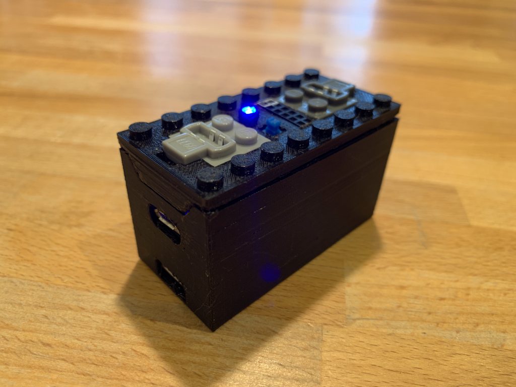
MTC4PF with battery
As depicted in the following picture, this solutions has the dimensions of of a standard LEGO power functions battery box. It contains a rechagable battery, an on/off switch, a status LED, two connectors for LEGO train motors and various LED outputs.

Building instructions and the STL files for the case can be found in the Casing section.
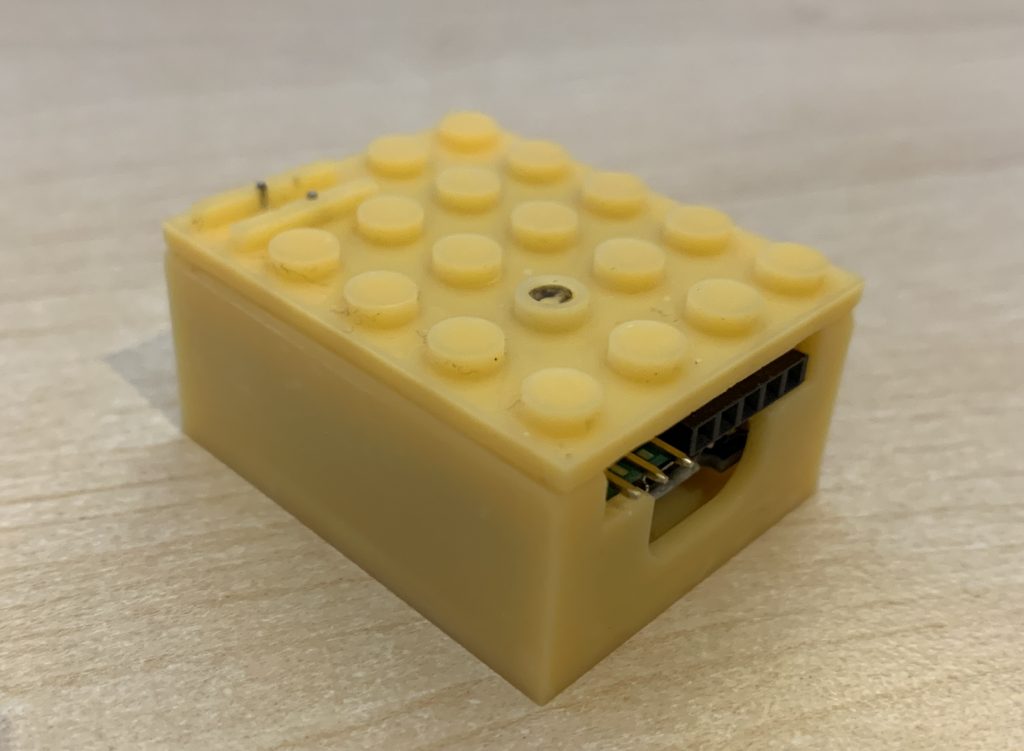
MTC4PF mini
As you see on the next picture, MTC4PFs can also be built in a small format. The version “MTC4PF mini” has a PCB especially designed for this controller. The case is a made with a resin 3d printer and has a very high quality. It features a status LED, two motor and two LED / multi-purpose outlets.
The size is only 4×5 studs wide and 2 standard LEGO bricks high.
Building instructions and the STL files for the case can be found in the Casing section.
Firmware preparations
The controller firmware is available from the Mattzobricks git repository.
Please follow the instructions on the firmware page.
Configuration
Before uploading the firmware, you need to configure it to make it work correctly.
Configuration preparations
Follow these steps:
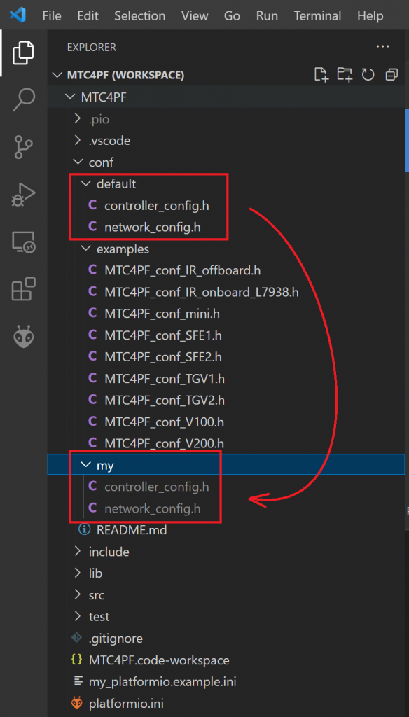
- Open the file explorer in VSCode and locate the directory “MLC/conf/”.
- There is a subfolder called “default/”. It contains two files:
- controller_config.h
- network_config.h
- Copy the mentioned subfolder into a new folder on the same level. The new folder must be named “my/” and has to contain the two files from “default/”.
In the VSCode user interface, this would look like this:
The idea behind this is, that the default configurations in the “default/” folder are under code control in the git repository. The “my/” subdirectory is excempt from code control. You may create your own configurations on this folder. When updating the firmware source code at a later point in time, your configurations will be safe and not be overwritten.
Now let’s have a look at the two configuration files on the “my/” folder and how to do the required configuration.
Network configuration
Open the file “network_config.h” in the “my/” folder. Then enter the correct values for your WiFi, the MQTT server, your logging options, and the password for updating the firmware via WiFi (OTA). Save the file.
Controller configuration
Open the file “controller_config.h” in the “my/” folder. The file is a couple of sections, in which you have to make entries in order to configure the locomotive (or, in very special cases, even multiple locomotives) that you want to control with the controller.
The following section describe the different sections of the controller_config.h file.
Locos
Configure the locomotives that the controller shall control. The meaning of the parameters are self-explanatory or explained in the configuration file.
The usual number of locos being controller by the controller is 1 (i.e., NUM_LOCOS = 1). The controller can control multiple locomotives only when using motor shields that are not directly connected to the controller by with the Lego Infrared Receiver 8884.
Motor shields
Configure the Motor Shields that the controller shall control. There are different types motor of supported shields:
- Directly connected motor shields (L298N, L9110). These motor shields are wired directly to the controller.
- Remote or virtual motor shields (Lego Infrared Receiver 8884).
The usual number of motor shields is again 1 (i.e., NUM_MOTORSHIELDS = 1). The controller is capable of controlling multiple motorshields per locomotive.
For each motor shield, you need to configure the wiring characteristics:
- Motor shield type of the directly connected motor shield and the pins used (details see code).
- Configuration of connected motors and lights for the Infrared “motor shield” including the pin used for the IR LED.
Train light configuration
In this section, a number of train lights (LEDs) can be defined.
Lights can be attached to the controller in three different ways:
- Directly to the controller via an ESP output pin (e.g. D0, D1 etc.),
- via motor shield (e.g. a set of Power Functions lights, LEGO set 8870 or compatible),
- via LEGO Infrared Receiver 8884 (usually also a set of Power Functions lights or compatible).
The lights can be mapped to functions and train light triggers in the next two sections.
Function mapping configuration
In this section, you can map Rocrail function button to switching train lights on and off.
Train light trigger configuration
In this section, you can map loco actions like “go forward”, “stop” and “go backward” to switching train lights on and off.
Controller configuration
In this section, you need to configure the some basic characteristics of the controller.
If a status LED is installed, you can enable it and assign the pin on which it is installed.
There are also some parameters for reporting battery level back to MQTT. As of release V1.0, this is not fully supported yet.
Network settings
In this section, you set if the eemergy break is triggered when the controller looses connection to MQTT. You can also set the hostname of the controller, and a deviating name for the syslog entries submitted by this controller.
Configuration examples
Before your start configuring the MTC4PF, it might be a good idea to have a look in the “conf/examples/default/” folder. This folder contains a couple of useful examples for the controller_config.h file.
Let’s have a look at some configuration examples.
A loco with L9110 and multi color headlights
File: “MTC4PF_conf_SF1.h”
A loco with L9110 motor shields and a multi color LED as headlight. The LED is lighting white when operating forward, and red when operating in reverse mode.
const int NUM_LOCOS = 1;

...

locoConf[0] = (MattzoLocoConfiguration) {
     .locoName = "Sante Fe",
     .locoAddress = 10020,
     .accelerationInterval = 100,
     .accelerateStep = 2,
     .brakeStep = 3
};

...

const int NUM_MOTORSHIELDS = 1;

...

msConf[0] = (MattzoMotorShieldConfiguration) {
        .locoAddress = 10020,
        .motorShieldType = MotorShieldType::L9110,
        .L298N_enA = 0,
        .L298N_enB = 0,
        .in1 = D1,
        .in2 = D2,
        .in3 = 0,
        .in4 = 0,
        .minArduinoPower = MIN_ARDUINO_POWER,
        .maxArduinoPower = MAX_ARDUINO_POWER,
        .configMotorA = -1,
        .configMotorB = 0,
        .irChannel = -1
};

...
The loco is called “Sante Fe”. It has the address 10020 in RocRail. Every 100ms (0,1 seconds), it will accelerate by 2% of the maximum power (20% per second) or brake with 3% of the maximum power (30% per second).
The motor shield is a L9110 type. Port A of the shield is connected to pins D1 and D2 on the controller. A train motor is connected to port A in reverse turning direction (-1). No device is connected on port B.
The locomotive features automatic, multi-colored train lights. The lights are connected to pins D5, D6 and D7. Please refer to the Train Light Configuration section in the example file. The parameters are more or less self-explanatory.
A loco with infrared receiver and Power Functions light
File: “MTC4PF_conf_IR_onboard_L7938.h”.
A single loco, “motor shield” is a LEGO Infrared Receiver 8884, one train motor and a Power Functions light are connected.
const int NUM_LOCOS = 1;

...

locoConf[0] = (MattzoLocoConfiguration) {
     .locoName = "L7938",
     .locoAddress = 7938,
     .accelerationInterval = 100,
     .accelerateStep = 2,
     .brakeStep = 5
...

const int NUM_MOTORSHIELDS = 1;

...

msConf[0] = (MattzoMotorShieldConfiguration) {
        .locoAddress = 7938,
        .motorShieldType = MotorShieldType::LEGO_IR_8884,
        .L298N_enA = 0,
        .L298N_enB = 0,
        .in1 = 0,
        .in2 = 0,
        .in3 = 0,
        .in4 = 0,
        .minArduinoPower = 0,
        .maxArduinoPower = MAX_ARDUINO_POWER,
        .configMotorA = 1,
        .configMotorB = 0,
        .irChannel = 0};
};

...

#define IR_LED_PIN D5

...
The loco is called “L7938” and has the address 7938 in RocRail. Every 100ms (0,1 seconds), it will accelerate by 2% of the maximum power (20% per second) or brake with 5% of the maximum power (50% per second).
The loco operates by sending commands to the LEGO Infrared Receiver 8884 via an infrared LED. One motor is installed on the red port (.configMotorA = 1). The receiver is tuned to channel 0. Please note that the constant MOTORSHIELD_TYPE must be set to MotorShieldType::NONE, as this motor shield is not directly attached to the controller.
The IR LED to control the LEGO Infrared Receiver 8884 is installed on pin D5.
Establish a USB connection to the controller
Before you can upload the firmware, a software driver needs to be installed for your board, so your PC can communicate with the ESP-8266. The required driver depends on your board. If you work with Microsoft Windows, you can try the “Windows CH340 Driver”. I found this driver on this webpage (as always, click and use on your own risk).
Uploading the firmware
To compile and upload the firmware, the platformIO plug-in in VSCode is used. Before uploading, you usually need to do some changes in a file called platformio.ini. Typical updates to this file include setting the COM port that the controller is connected to.
As this file is under source code control as the default network and controller configuration files, we will use a different file for our private configuration changes. To do this, you need to copy the file “my_platformio.example.ini” into a new file, which you need to call “my_platformio.ini”. This file will be excluded from source code control. Thus, is will survive later version upgrades.
Setup in Rocrail
To set-up a train controller in Rocrail, open Rocview and navigate to menu Tables / Locomotives. Choose the locomotive that you want to configure or create a new one.
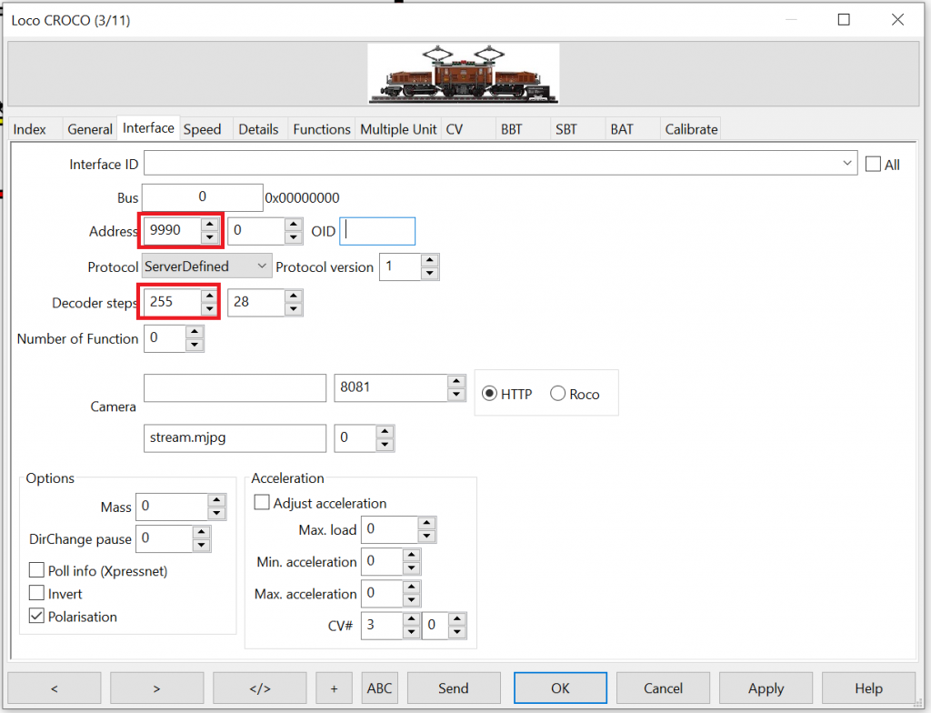
Navigate to tab “Interface” and configure the loco address as specified in the firmware configuration file above. Then set the “Decoder Steps” value to 255. Please note that the MattzoControllerId is irrelevant for the loco setup.
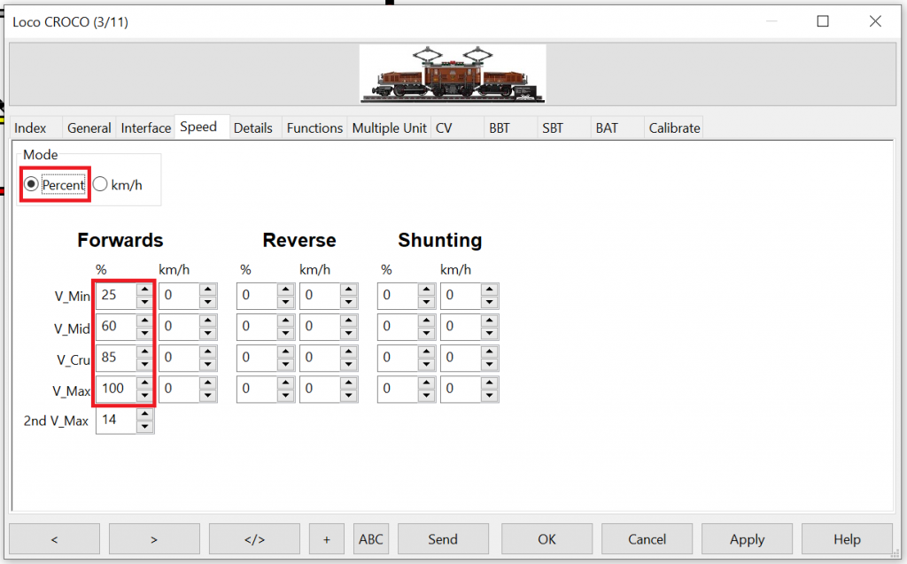
Navigate to the “Speed” tab, and choose “Percent”. Enter useful motor power values for the different speed levels (trial and error):
Defining speed in Rocrail is a complex matter. More information about this topic can be found here.
There is a lot of additional configuration options for trains in Rocrail. Please refer to the Rocrail documentation for more information.
Enjoy!
Support for the 9V RC Train System
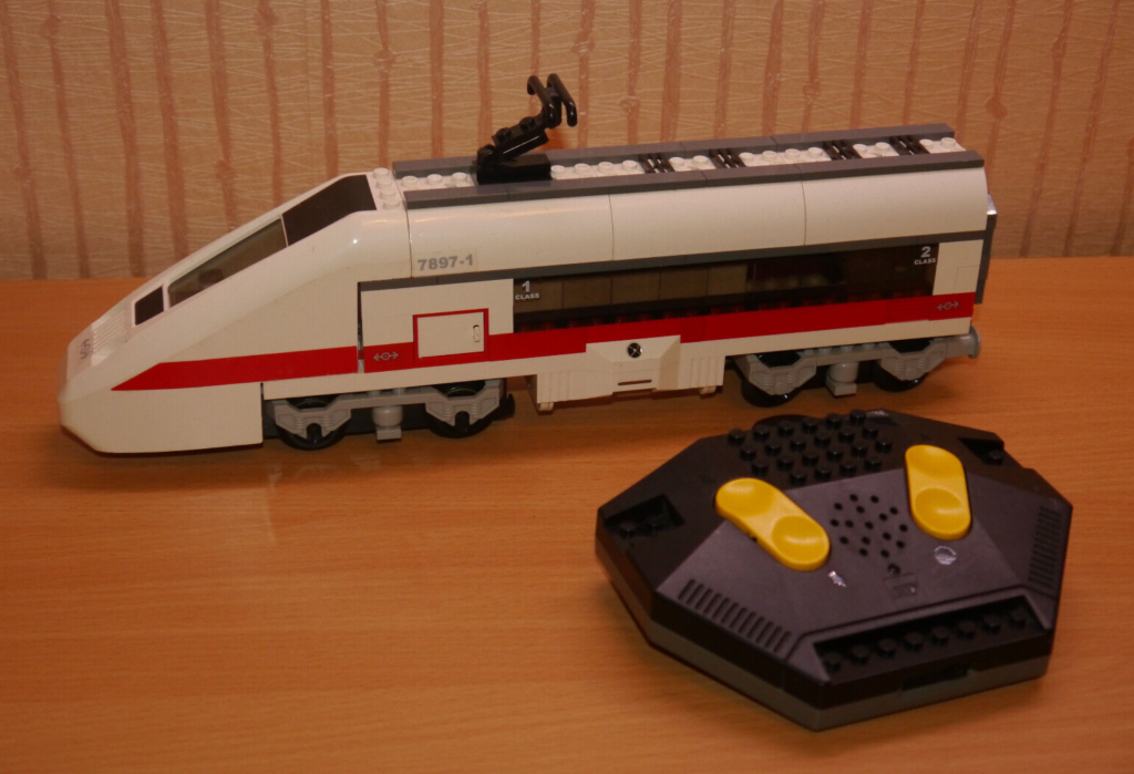
About the 9V RC Train System
Back in 2005, LEGO had released the beautiful #7987 Passenger Train and #7898 Cargo Train sets. These were using a new rc train base with infrared receivers. This technology was used as an interim technology only, and was replaced by the more powerful Power Functions system shortly after.
The good news is, that you might be successfull in integrating your 9V rc train base into the MTC4PF with very limited effort.
Bad news is, that there is no guarantee that you will be successfull. The success depends on the firmware version that is on the rc train base (Lego part number 55455c01). There are at least two different firmware versions, and the older ones are not supporting it. We haven’t found any external indication to say wether it will work or not. Only when we were opening it and checking the board, we’ve learned that at least the ones from 2005 are not supporting the required commandset. We believe that the best and only way to find out if it works for your train, is to test it and see if it works.
As the support is not guaranteed, and the rc train base was only an intermediate step towards the more powerful Power Functions technology, the base is quite limited. This is why the solution did not make it into the master branch of the MTC4PF source code repository.
If you want to give it a try, you need to modify the source code a little bit.
What do you need to do?
It is quite easy: You just need to edit a number of lines in the file <MattzoPowerFunctions.h> that you’ll find in ./src/mlc_lib/MattzoPowerFunctions:
Find these lines:
// By spec CHECKSUM is a XOR based on the 4-bit triplet you are sending
#define PF_CHECKSUM() (0xf ^ _nib1 ^ _nib2 ^ _nib3)

#define PF_START_STOP PF_IR_CYCLES(39)
#define PF_HIGH_PAUSE PF_IR_CYCLES(21)
#define PF_LOW_PAUSE PF_IR_CYCLES(10)

#define PF_MAX_MESSAGE_LENGTH PF_IR_CYCLES(522) // 2 * 45 + 16 * 27
And replace them with these lines instead:
// By spec CHECKSUM is a XOR based on the 4-bit triplet you are sending
#define PF_CHECKSUM() (0xf ^ ((_nib1 + _nib2 + _nib3) % 0x10))

#define PF_START_STOP PF_IR_CYCLES(74)
#define PF_HIGH_PAUSE PF_IR_CYCLES(35)
#define PF_LOW_PAUSE PF_IR_CYCLES(15)

#define PF_MAX_MESSAGE_LENGTH PF_IR_CYCLES(724) // 2 * 74 + 16 * 36
Configure it like a one motor (A) configuration on an 8884, compile and deploy it to an ESP. Than you will see if you have a working configuration. The rc train base has two infrared receivers (one on the left, one on the right) on the crossed notches in the middle (next to the powerswitch). If the red LED indication is starts blinking periodically (every second) that your board supports the functions and you can use it in Rocrail.
For the rc train bases that, I have that are not supporting it, I found a solution to build a solution with an ESP and a L9110. So I can switc to control the train with the original infrared controller or a Mattzo integration of the train into Rocrail. In any case the solution uses the onboard battery pack of the train base.
Good luck !
Hallo ich habe nun LIpos Laufen mit 1400MHA. Ein Ladeadapter und schalter für die lock. Über usb C .
Bauteile:
Lade Bauteil 18650 TYP USB C Mit lade schutz. ( bei ali )
Drucktastenschalter on-Off on-on Mini Wippschalter ( bei ali )
3,7 V 1800 mAh Lipo Batterie oder 3,7 V 1400 mAh Lipo Batterie ( bei ali )
Schaltplan habe ich von :
https://www.youtube.com/watch?v=hxfUpI8iMJM
Statt den Sbrick habe ich gleich alles an den esp und motorteiber laufen läuft super mit 2 motoren und langem zug Teste nun die 1800mha