
Please read the general section first!
History
In the first releases of the firmware, there were different MattzoControllers for switches, light signals and sensors, each with a different firmware. These MattzoControllers were named as follows:
- MattzoSwitchController,
- MattzoSignalController,
- MattzoSensorController.
With increasing number of configuration options and features, the maintenance of these different MattzoControllers became increasingly tedious. Another aspect was, that you could only connect a single type of component to one of the controllers.
For these reasons, these specialized MattzoControllers were bundled into a single MattzoController called MattzoLayoutController (MLC).
At a later stage, support for level crossings, bascule bridges and speedometers was integreated into the MLC firmware.
Purpose
The MattzoLayoutController serves the following hardware components:
- servos,
- LEDs and
- digital sensors (usually reed sensors, but any other digital sensors also work).
These hardware components can be attached directly to the pins of the controllers or via port extenders.
The following logical objects can be mapped to the mentioned hardware components:
- switches,
- signals,
- sensors,
- level crossings,
- bascule bridges,
- speedometers.
All of the logical objects above have a direct representation in Rocrail (except the speedometer).
Functional Description
The MattzoLayoutController services hardware layout components like switches, signals and sensors.
One MattzoLayoutController can handle up to 8 switches or 4 standard light signals or 8 sensors or any combination of it. The standard configuration contains a combination of 4 switches, 1 light signal (2 LEDs) and 2 sensors. Other combinations are possible.
The MattzoLayoutController can be extended with a port extender type PCA9685. When using one port extender, 6 sensors, 22 switches or 11 signals can be controlled. Port extenders can be chained, expanding the number of connectable components respectively.
A very nice version of a MLC is the “MLC mega”. It can connect 16 sensors, 16 switches and 8 standard light signals in a “plug and play” fashion.
Wiring
Required Components
To build a MattzoLayoutController, you need to following components:
- I/O board with micro controller. We have used a NodeMCU Amica Modul V2 ESP8266 ESP-12F. Similar modules should work as well.
- LED for optional status LEDs, possibly with some resistors.
- PCA 9685 port extender board (optional).
- MCP23017 port extender board (optional).
- Reed Sensors and LEDs for signals (see MattzoSensorController and MattzoSignalController).
- Basic stuff like bread board, wires etc.
Standard Wiring without PCA9685
The following diagram shows the wiring of the MattzoLayoutController as configured in the standard configuration (configuration file “MLC/conf/default/controller_config.h”):
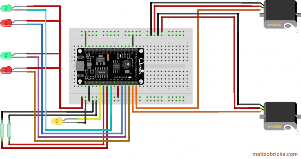
Switch Motors can be connected on pins D0 and D1.
Twos signals can be connected to pins D2/D3 and D4/D5. Note that the pins are actually pulling the voltage down to ground when activated, so the cathode of the LEDs needs to be connected to them. The anode of the LEDs must be connected to the plus terminal of the LED.
D6 and D7 are configured for sensors.
On pin D8, a status LED can be attached. The status LED indicates to WiFi connection status, the MQTT connection status and lights up when one or more sensors are triggered. The status LED is very handy in practice. Therefore, this wiring option is recommended.
Please note that pin D8 must not be pulled up when the controller starts up, or the controller will not boot correctly. Only if you know exactly what you are doing, the port may be used for other purposes as well, e.g. for reed sensors or to connect the anode of a LED.
A similar rule applies for pins D3 and D4. They must not be pulled down during start-up, or the controller won’t boot.
MLC with Port Extenders
The number of ports of the MLC can be significantly extended by using port extenders. PCA9685 and MCP23017 are supported.
A point to start is the example configuration file “MLC_conf_mega.h”, which is using 1 PCA9685s and 2 MCP23017s.
Port Extender PCA9685
To extend the number of switch and LED ports, PCA9685 port extenders can be attached to the MattzoLayoutController. Chaining (attaching more than one PCA9685) is possible – see the “Chaining PCA9685 port extenders” section below.
The PCA9685 supports PWM output (servo control) and digital output (LED control). It can not be used for input, so connecting sensors to the device is not possible.
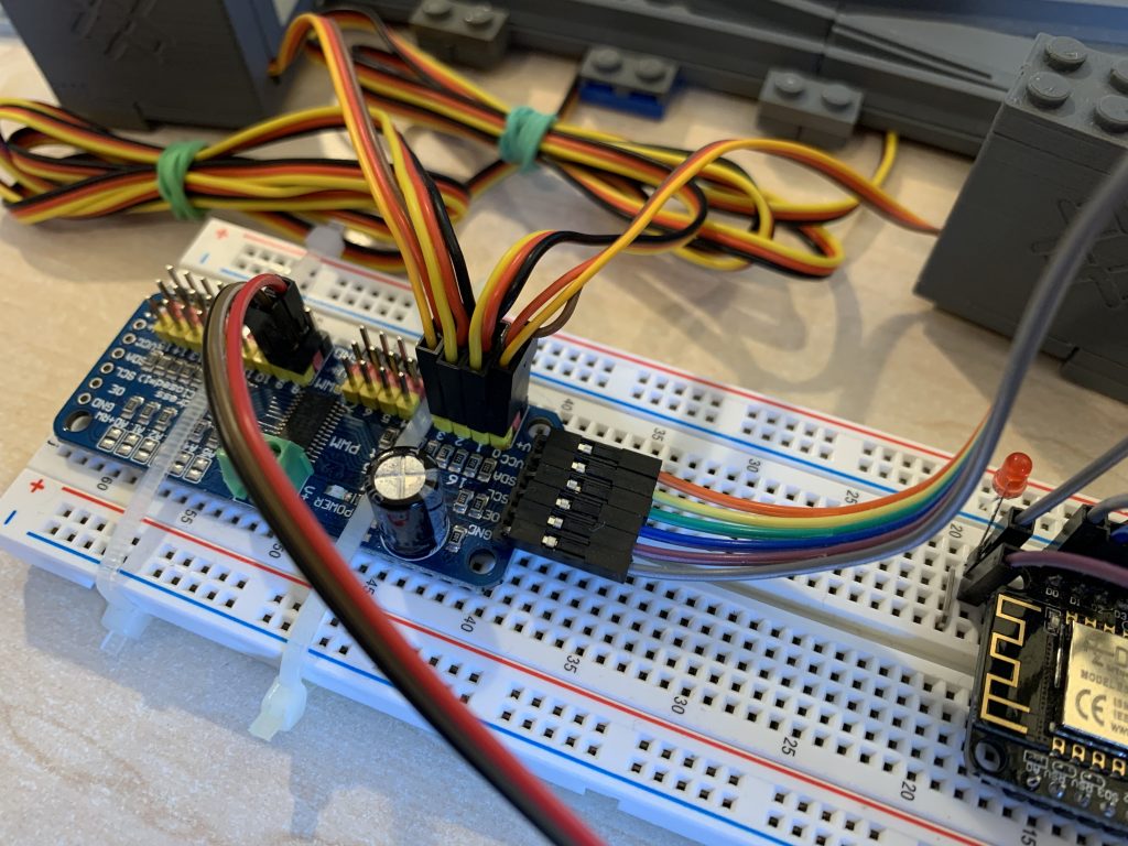
The following diagram shows an example of how to wire the MattzoLayoutController with one PCA9685. For demonstration, one switch motor, one signal and one reed sensor are attached to the MattzoLayoutController:
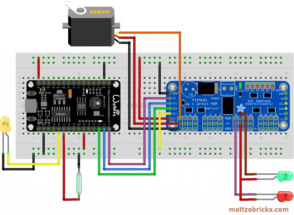
In this configuration, eight switch Motors can be connected to the PCA9685 on ports 0 to 15.
Alternatively, eight standard signals (16 LEDs) can be connected to the PCA9685 on ports 0 to 15. Note that the PWM pins are actually pulling the voltage down to ground when activated, so the cathode of the LEDs need to be connected to them. The anode of the LEDs must be connected to the plus terminal of the LED.
On pin D0, the OE-Pin of the PCA9685 is connected. It is used to switch the PWM terminal on the connector bar of the PCA9685 on and off. This may be useful to switch the power supply of motors off after switches have been switched, as this may prevent blocking servo motors from overheating in case of technical problems. Nevertheless, this option is not recommended for all situations, as using the OE-Pin if not compatible with LED attached to the PCA9685.
Pins D3, D4, D5, D6 and D7 can be configured alternatively, e.g. for sensors. Additional sensors can be connected to D0 (if OE-Pin not used; attention: pull-down resistor required!), and D8 (if the status LED option is not used; attention: internal pull-resistor is pulling the pin up, not down). For more details using pins for sensors, see MLC with sensors.
On pin D8, a status LED can be attached. The status LED indicates to WiFi connection status, the MQTT connection status and lights up when one or more sensors are triggered. The status LED is very handy in practice. Therefore, this wiring option is recommended.
Please note that pin D8 must not be pulled up when the controller starts up, or the controller will not boot correctly. Only if you exactly what you are doing, the port may be used for other purposes as well, e.g. for reed sensors or to connect the anode of a LED.
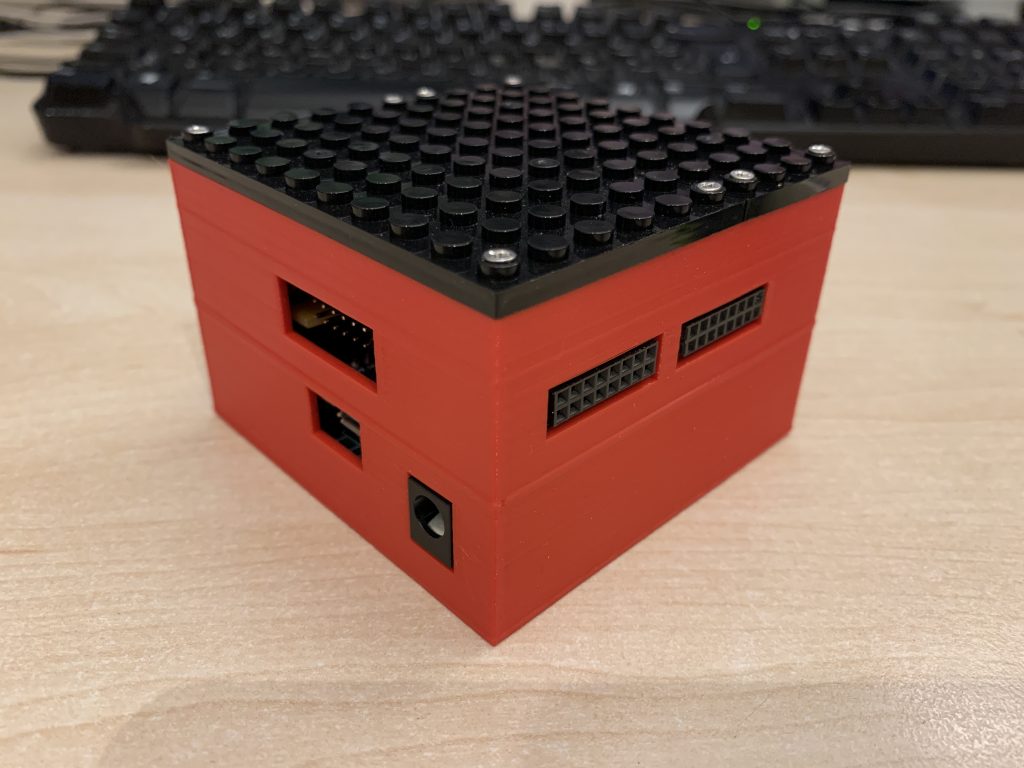
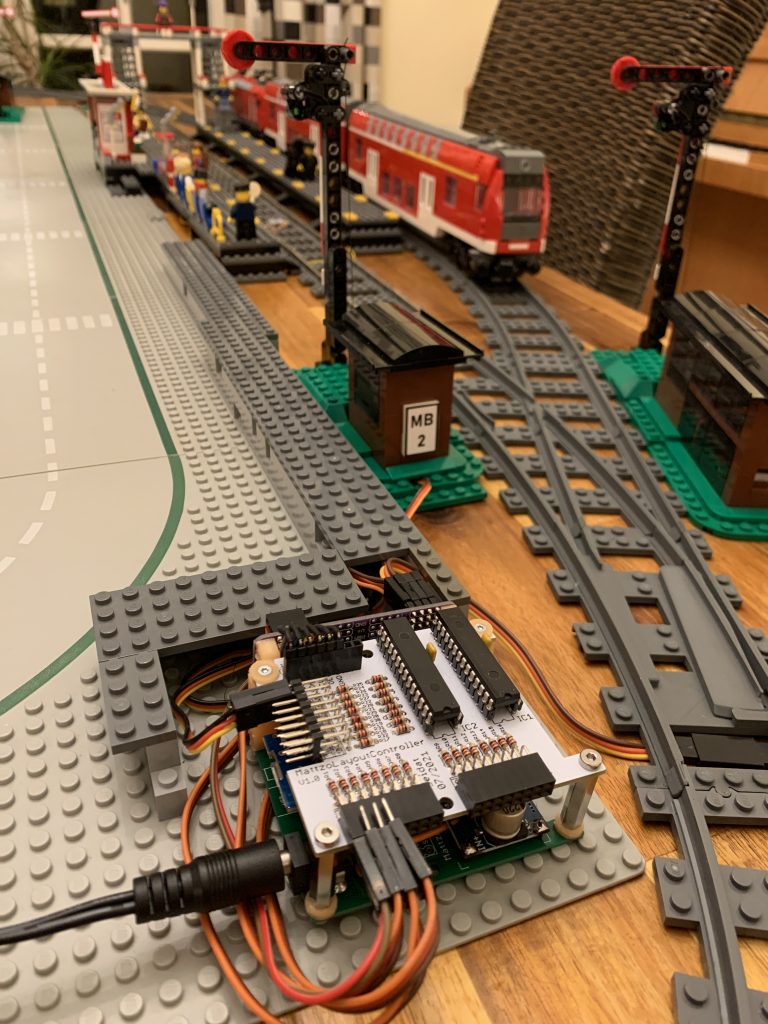
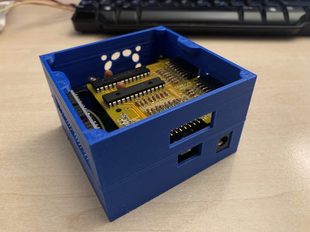
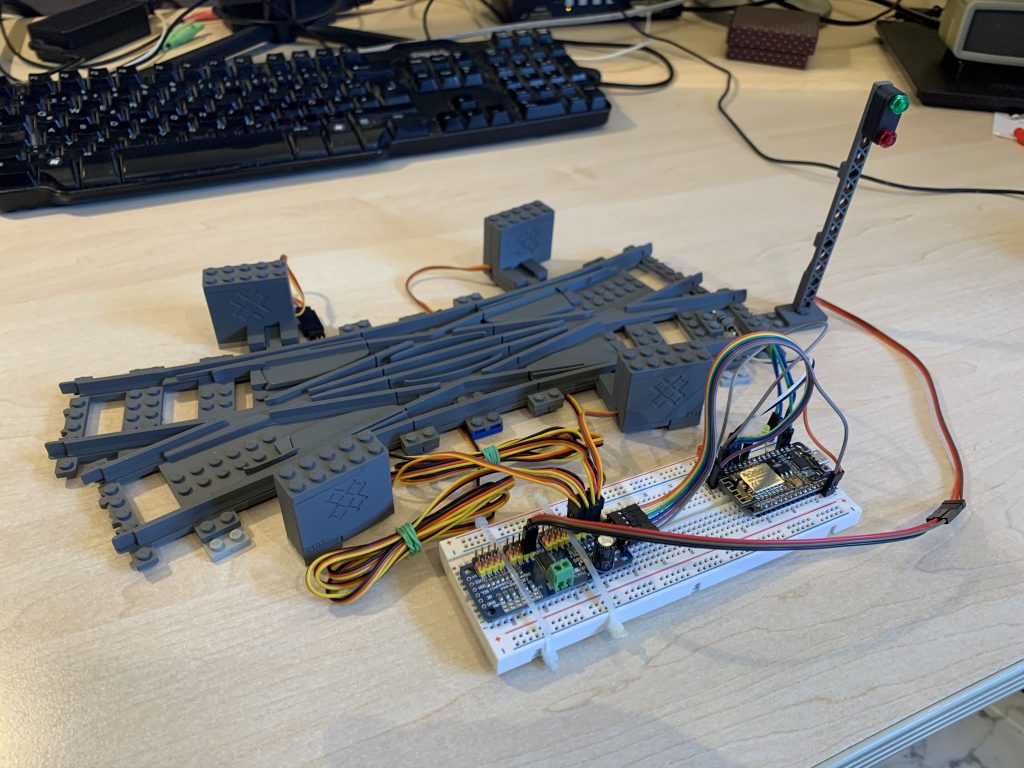
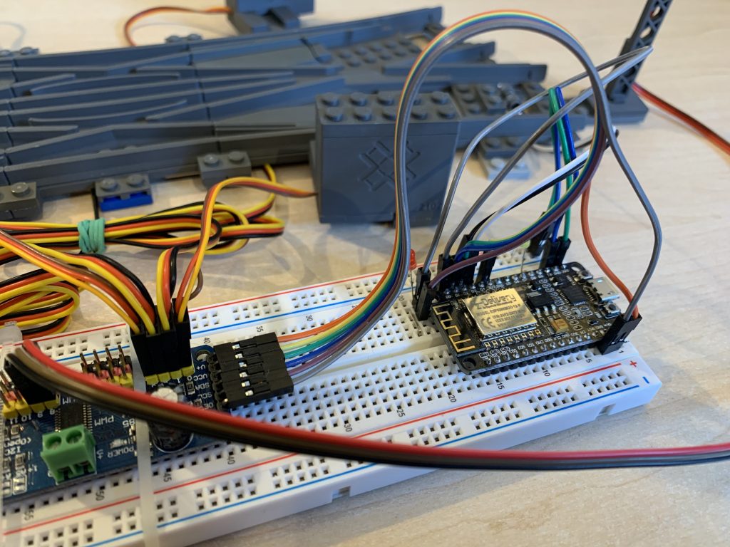
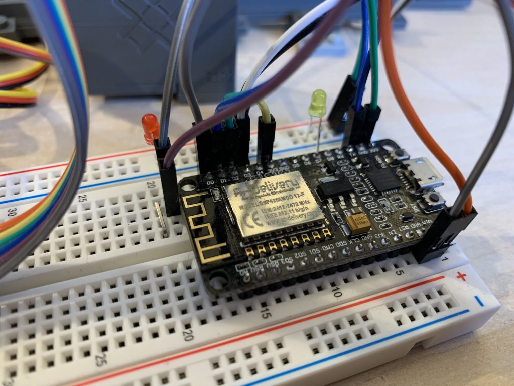
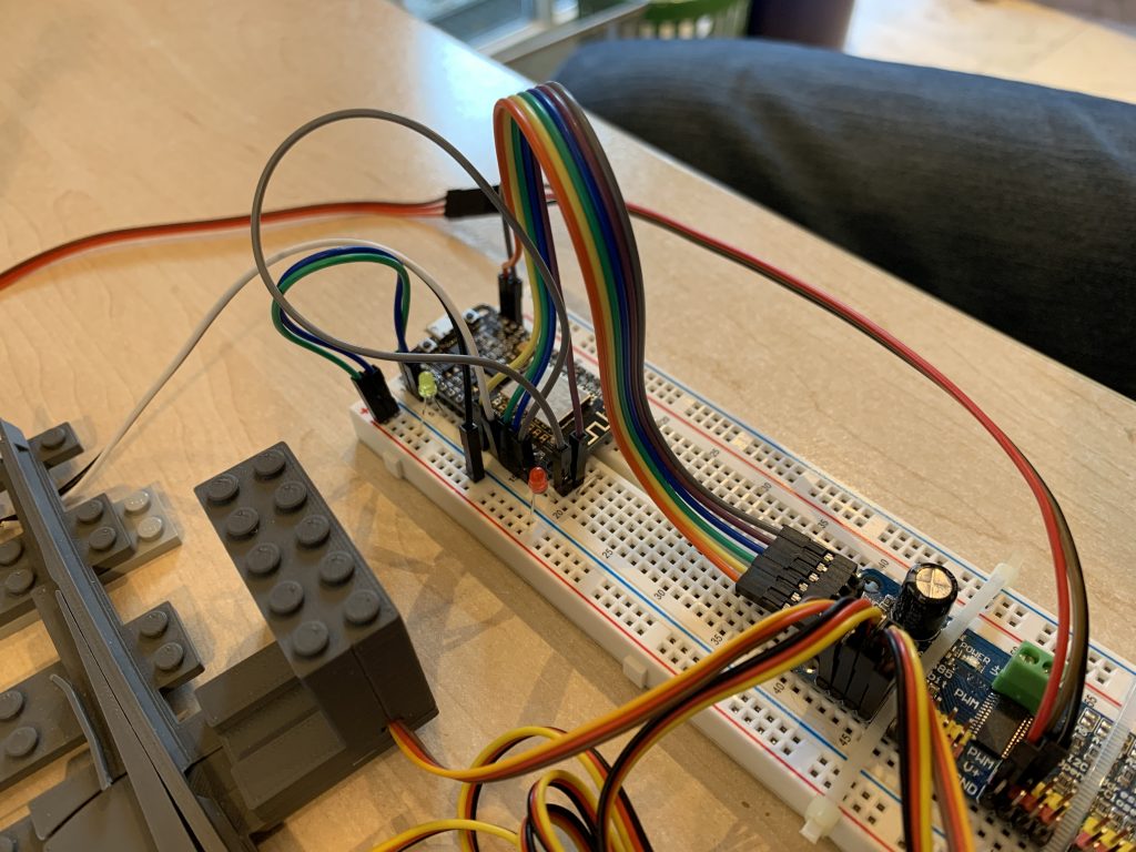
The following pictures show a MattzoLayoutController with PCA9685. A double slip switch with four switch motors, one signal and one sensor are attached. A small yellow status LED is attached to pin D8. To monitor the operation of the OE-Pin, a small red LED is also installed:
Port Extender MCP23017
To extend the number of ports for signal LEDs and sensors, MCP23017 port extenders can be attached to the MattzoLayoutController. Chaining (attaching more than one port extender) is possible – see the “Chaining port extenders” section below.
The MCP23017 supports digital output (LED control) and digital input (sensors). It can not be used for analog or PWM output, so connecting servos or fading LEDs to the device is not possible.
The following diagram shows an example wiring of the MattzoLayoutController with one MCP23017. For demonstration, two reed sensors are attached to the MattzoLayoutController:
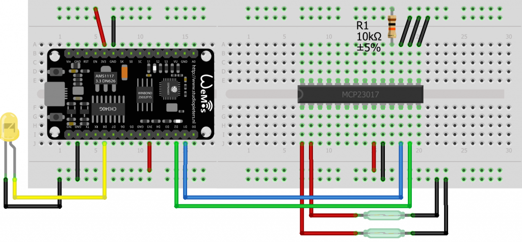
In this configuration, 16 sensors can be connected to the MCP23017 on ports 0 to 15.
The following example uses two MCP23017:
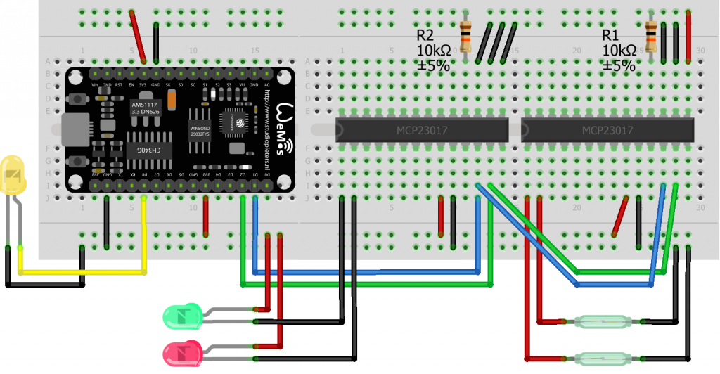
For more details of the wiring refer to the PCA9685 section above. Attaching a MCP23017 is similar to attaching a PCA9685 in most aspects.
Chaining Port Extenders
Chaining (attaching more than one port extender) is possible. Basic information and how to setup addressing of chained PCA9685 or MCP23017 port extenders can be found on various sources on the web, for example here.
Power Supply
A MattzoLayoutController often needs more electrical power compared to other MattzoControllers, especially when servos are connected to the controller. Using port extenders with a lot of LEDs may also consume at lot of power.
To avoid brown outs, a power source of around 5V and at least 2A is required. From four switch motors onwards, I would recommend a power supply of at least 3A.
We have made very good experiences with a power supply device from Pollin (dealer in Germany) that delivers 5,9V at 4 Ampère. With a device of that you are on the safe side. I am sure that these devices will be available throughout the globe if you look around a little bit.
Casing
The is a very powerful standard hardware version of the MattzoLayoutController called “MLC mega”. It features specially designed PCBs, a 3d printed case, a connector for a strong power supply, and has three build-in port extenders (one PCA9685 and two MCP23017s).
The MLC mega is able to connect:
- 16 servos (e.g. for 16 switches)
- 16 LEDs (e.g. for 8 standard light signals), and
- 16 sensors.
The controller also manages all other land based components like form signals, level crossings and bascule bridges.
The following pictures shows a picture of the MLC mega.
Information of how to build your own MLC mega can be found on the do-it-yourself page.
Firmware preparations
The controller firmware is available from the Mattzobricks git repository.
Please follow the instructions on the firmware page.
Configuration
Before uploading the firmware, you need to configure it to make it work correctly.
Configuration preparations
Follow these steps:
- Open the file explorer in VSCode and locate the directory “MLC/conf/”.
- There is a subfolder called “default/”. It contains two files:
- controller_config.h
- network_config.h
- Copy the mentioned subfolder into a new folder on the same level. The new folder must be named “my/” and has to contain the two files from “default/”.
In the VSCode user interface, this would look like this:
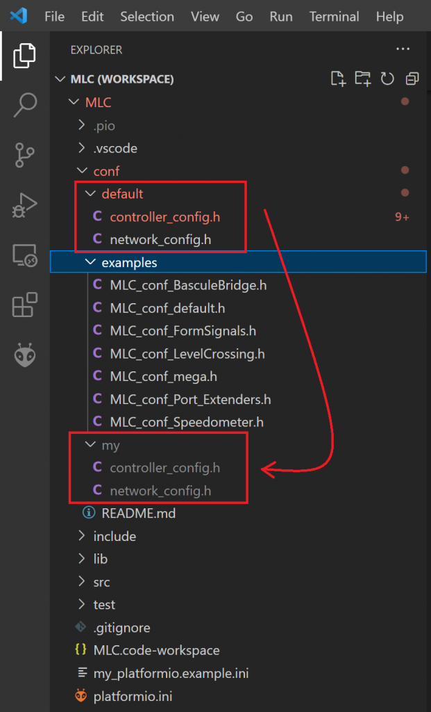
The idea behind this is, that the default configurations in the “default/” folder are under code control in the git repository. The “my/” subdirectory is excempt from code control. You may create your own configurations on this folder. When updating the firmware source code at a later point in time, your configurations will be safe and not be overwritten.
Now let’s have a look at the two configuration files on the “my/” folder and how to do the required configuration.
Network configuration
Open the file “network_config.h” in the “my/” folder. Then enter the correct values for your WiFi, the MQTT server, your logging options, and the password for updating the firmware via WiFi (OTA). Save the file.
Controller configuration
Open the file “controller_config.h” in the “my/” folder. The file is diveded into a couple of sections, in which you have to make entries in order to configure the hardware components and logical objects.
The specific configuration sections which you have to configure depend on the hardware components conncted and logical objects that you want to control with your MLC. More detailed information about the configuration is given in the application specific sub-pages for the MLC.
Establish a USB connection to the controller
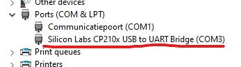
Before you can upload the firmware, a software driver needs to be installed for your board, so your PC can communicate with the ESP-8266. You can find the required driver and documentation here:
Then you attach your PC to your pc using a USB cable. Windows will recognize the device and install it. Now you can determine the COM-port your ESP-32 is connected to. For Windows 10/11 you can find this in Device Manager. Search for this device under Ports (COM & LPT):
Uploading the firmware
To compile and upload the firmware, the platformIO plug-in in VSCode is used. Before uploading, you usually need to do some changes in a file called platformio.ini. Typical updates to this file include setting the COM port that the controller is connected to.
As this file is under source code control as the default network and controller configuration files, we will use a different file for our private configuration changes. To do this, you need to copy the file “my_platformio.example.ini” into a new file, which you need to call “my_platformio.ini”. This file will be excluded from source code control. Thus, is will survive later version upgrades.
Rocrail setup and specific deployment scenarios
Follow the following instructions for more information about controlling specific logical objects with the MattzoLayoutController:
Enjoy!
Hallo,
ich beschäftige mich gerade mit ein genauso Thema und würde Ihnen gerne frage ob Sie mir ein Programm für diese Mattzolayoutcontroller with PCA 9685 Port Extender.
Support for PCA9685 Port Extender is integrated in the firmware.