
Please read the general section first!

General information about switches
This video contains general information about automated switches in the Mattzobricks Train Automation System:
Purpose
The MattzoLayoutController (MLC) is designed to receive switch commands from Rocrail via the MQTT broker and flip a switch into the requested direction.
Functional Description
When Rocrail request a switch to turn into a specific direction, it communicates this as a command via the MQTT broker. The MattzoController receives this command and evaluates, if the command is relevant for the specific controller (i.e. if the switch is connected to this controller).
The switch command contains the following data:
- the MattzoControllerId
- the Rocrail port to which the switch motor (servo) is connected to
- the requested direction of the switch (straight or thrown)
The number of switches that can be attached to one MattzoController depends of the number of servos that the switch requires:
- A standard switch has one servo, and needs one Rocrail port.
- A triple switch has two servos, and needs two Rocrail ports.
- A double slip switch has four servos, and needs two Rocrail ports (two servos share one Rocrail port).
The number of switches that can be controlled by a MLC depends on the number of servos that the MLC can control. This number depends on version of the MLC that you want to build.
A MLC mini can control by fault 2 servos, thus it can control 2 standard switches or one triple switch. The MLC mini configuration can be changed so that it can control up to 8 servos, and the corresponding number of switches.
A MLC mega controls up to 16 servos, thus it can control 16 standard switches, 8 triple switches or 4 double slip switches (or any combination of it).
Wiring
The following sketch shows the wiring of the MattzoLayoutController with 8 switch motors attached:
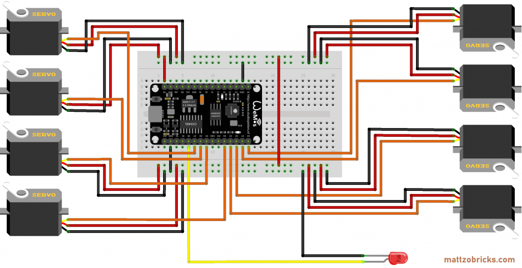
As you can see, you simply connect the PWM wire (usually orange) of the servos to the output pins D0 to D7, connect the red wire (plus) to VIN and the black wire to GND (ground).
Required components:
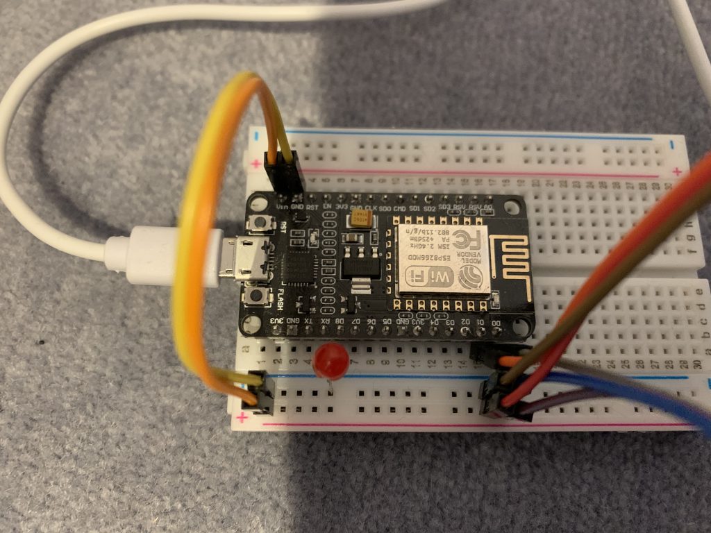
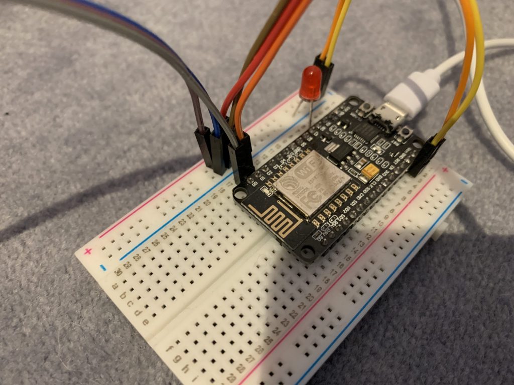
- I/O board with micro controller. We have used a NodeMCU Amica Modul V2 ESP8266 ESP-12F. Similar modules should work as well.
- Basic stuff like bread board, wires etc.
An optional LED can be installed on pin D8 to monitor the correct operation of the controller. It is indeed a good idea to connect the LED to D8, because this pin must necessarily be pulled down or the controler will not boot correctly.
Power Supply
Sufficient power supply is crucial because the servo motors require some power to flip the switches. If the power supply is to weak, the voltage in the micro controller goes down, which can cause a crash of the controller. We have made pretty good experiences with power supplies that deliver 2 amps.
The controller can be powered up with a simple USB charger over USB or some other power supply of similar voltage that is connected to the VIN and GND pins of the controller. If you use a different power source, voltage should be in the range between 4.5V and 6V.
Firmware Configuration
Please read the MLC general page first.
To configure the firmware configuration, you need to edit the controller configuration file (controller_config.h).
MLC mini and MLC mega have standard configurations that do not need to be changed to standard switches and triple switches. You need to change the standard configuration only if you are using double slip switches (see below).
The configuration file has two relevant sections:
- SERVO WIRING CONFIGURATION, and the
- SWITCH CONFIGURATION.
The sections are clearly marked in the standard configuration file, and the different parameters are explained (as of firmware V1.1 in file MLC_types.h) with code comments.
Servo wiring configuration
In this section, the servos are defined that are attached to the controller. It is the physical part of the switch definition.
The following example stems from the MLC mini standard configuration:
// SERVO WIRING CONFIGURATION
// Servos are used for motorizing switches and form signals
// Number of servos
#define NUM_SERVOS 2

TServoConfiguration servoConfiguration[NUM_SERVOS] =
{
    {
        .pin = D3,
        .pinType = 0,
        .detachAfterUsage = true
    },
    {
        .pin = D4,
        .pinType = 0,
        .detachAfterUsage = true
    }
};
In the example, two servos are defined. The first one is attached to pin D3, the second one to D4. The servos are attached directly to the controller (pinType = 0), and after having moved the servo, the servo will be “detached” (switched off).
Please note that the NUM_SERVOS constant must equal the number of defined servos in the array.
Switch configuration
In this section, the switches operated by this controller are defined. The definition contains the mapping of the switch to the servos defined in the servo wiring configuration, and their port in Rocrail. It is the logical part of the switch definition.
The following example stems from the MLC mini standard configuration:
// SWITCH CONFIGURATION
// Number of switches
#define NUM_SWITCHES 2

TSwitchConfiguration switchConfiguration[NUM_SWITCHES] =
{
    {
        .rocRailPort = 1,
        .servoIndex = 0,
        .servo2Index = -1,
        .servo2Reverse = false,
        .triggerSensors = false,
        .sensorIndex = { -1, -1 }
    },
    {
        .rocRailPort = 2,
        .servoIndex = 1,
        .servo2Index = -1,
        .servo2Reverse = false,
        .triggerSensors = false,
        .sensorIndex = { -1, -1 }
    }
};
NUM_SWITCHES constant must equal the number of defined switches in the array. In the example, two standard switches are defined. The first one relates to rocrail port 1 in rocrail, the second one to rocrail port 2.
The first one uses the first servo (servoIndex 0) in the servo wiring configuration, the second one the second servo (servoIndex 1).
All other parameters are described further below.
Rocrail Setup
For general setup instructions please refer to the “General” section.
Standard Switch
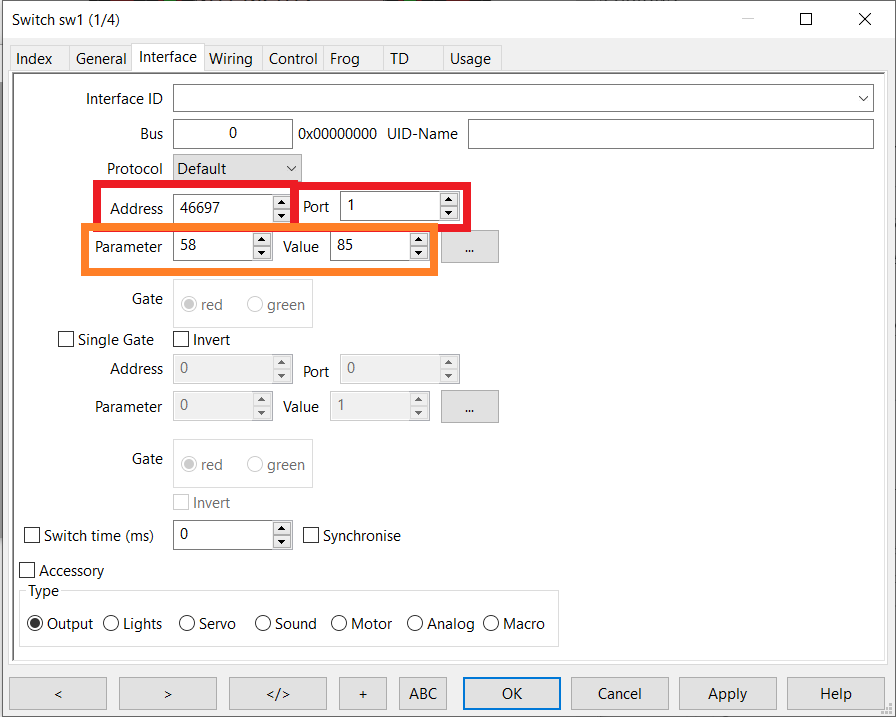
To setup a standard switch in Rocrail, locate the switch on the plan, click it with the right mouse button and select “Properties”. Then navigate to the interface tab of the switch properties dialog.
The MattzoControllerID must be entered as “Address” parameter, and the rocrail port to which the switch is connected as “Port”.
In Rocrail, we also define the required rotation angles of the servo to achieve the “straight” and “thrown” direction of the switch. This is very handy, because these values are different for each servo. 75 and 85 are good starting values for Trixbrix servos.
Enter the minimum angle of the switch servo motor into the “Parameter” field, and the maximum angle into the “Value” field. Then test the switch (leave the dialog and click on the switch to operate it). Good values require a bit of trial and error
ALL OTHER INFORMATION ON THIS PAGE CAN BE NEGLECTED AND HAS NO MEANING!
After setting up everything, you should test the switch. Simply set Rocrail in the “operate” mode and click the switch symbol. If the switch orientation is incorrect (switch is thrown when the symbol shows straight), simply exchange the values for “Parameter” and “Value” in the Rocrail configuration.
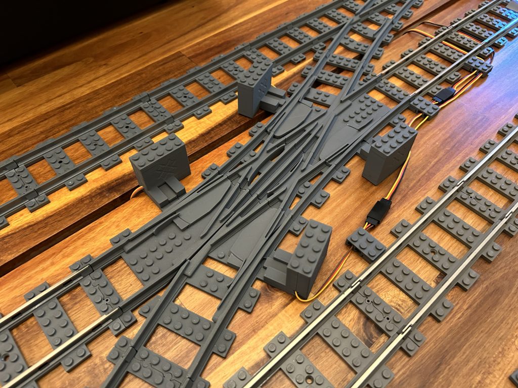
Triple Switch
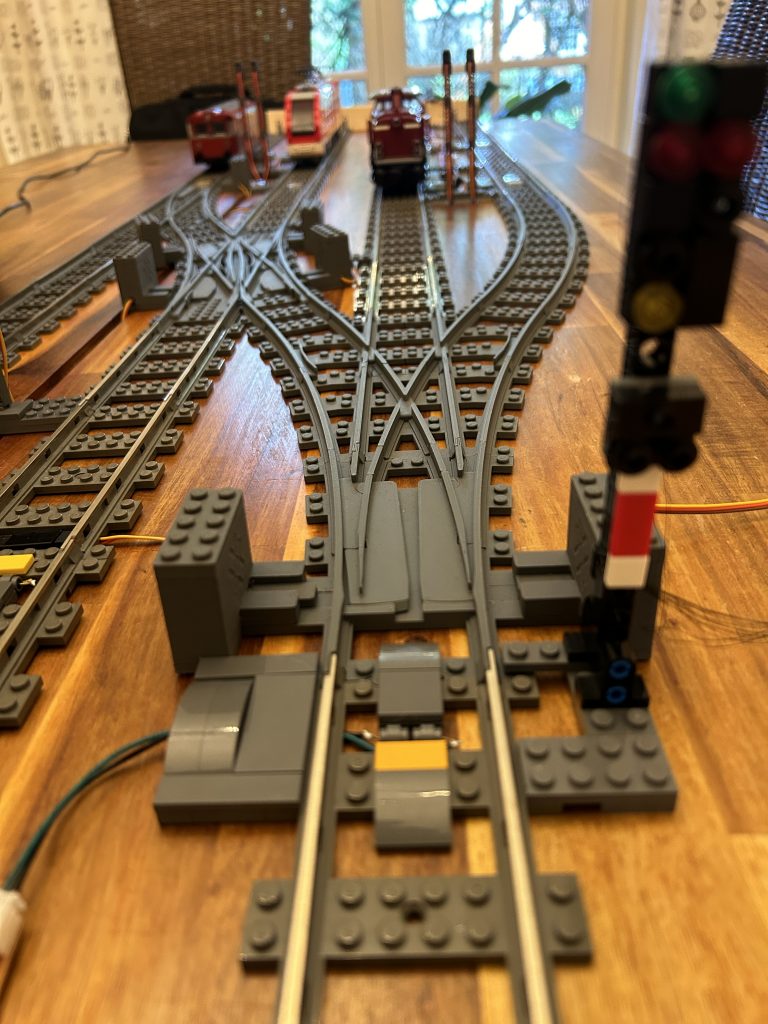
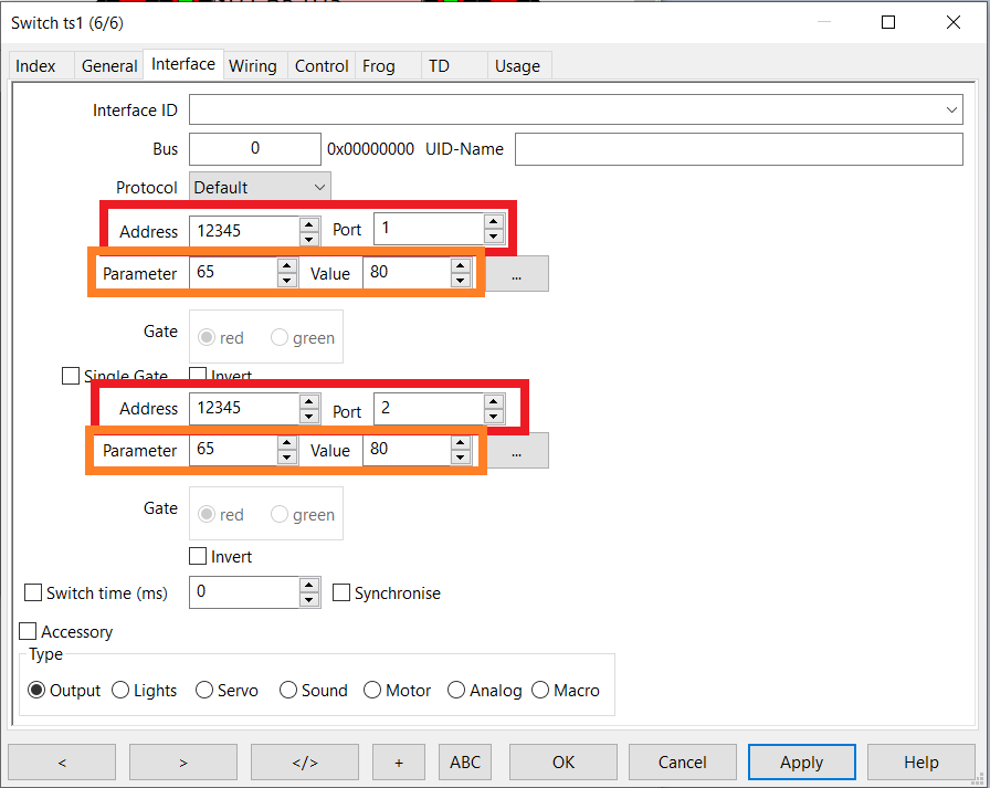
To setup a triple switch in Rocrail, navigate to the interface tab of the switch definition. A triple switch can be seen as a combination of two switches. They require two logical switch objects in the MLC configuration, each using a different servo.
The MattzoControllerID must be entered as “Address” parameter, and the ports of the two switches are defined in the MLC configuration
As for standard switches, enter the minimum angle of the switch servo motors into the “Parameter” fields, and the maximum angle into the “Value” fields.
ALL OTHER INFORMATION ON THIS PAGE CAN BE NEGLECTED AND HAS NO MEANING!
After setting up everything, you should test the switch. The idea is similar to the standard switch, just that you have two servos to care about.
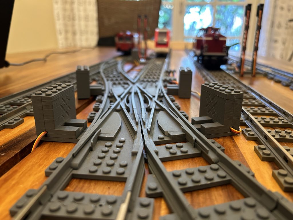
Double Slip Switches
Setting up a double slip switches is a bit more tricky.
Principle
Rocrail considers a double slip switch (dss) as two switches that are logically combined. Each side of the double slip switch has its own Rocrail port. Each side has two servos. The servos of each side are always used synchronously.
The following picture illustrates the idea (with example values):
- The left side (green) has Rocrail port 1001, and the associated servos 0 and 1. When switching, both servos move synchronously.
- The right side (red) has Rocrail port 1002, and the associated servos 2 and 3. When switching, both servos move synchronously.
The overall switch direction results from the settings of both Rocrail port 1001 and 1002. In the example below, the switch is set to “straight” (vehicles may pass straight from left to right and vice versa).

The idea is a bit tricky to understand at first glance, but you’ll get behind it once you use it in practice.
Firmware configuration for double slip switches
If you use an MLC mega with a recent firmware, no configurationi change is required. Double slip switches are defined in the MLC mega standard configuration by default (Rocrail ports 1001 to 1008).
MLC minis require a configuration change. First, you need to extend the servo wiring configuration so that you have four servos.
A double slip switch requires two logical switch objects in the MLC configuration. Each of them has a Rocrail port as described above.
This is an example (imagine, four servos were defined in the servo wiring configuration):
// SWITCH CONFIGURATION
// Number of switches
#define NUM_SWITCHES 2

TSwitchConfiguration switchConfiguration[NUM_SWITCHES] =
{
    {
        .rocRailPort = 1001,
        .servoIndex = 0,
        .servo2Index = 1,
        .servo2Reverse = false,
        .triggerSensors = false,
        .sensorIndex = { -1, -1 }
    },
    {
        .rocRailPort = 1002,
        .servoIndex = 2,
        .servo2Index = 3,
        .servo2Reverse = false,
        .triggerSensors = false,
        .sensorIndex = { -1, -1 }
    }
};
The second servo of each logical switch is defined with the “servo2index” parameter. As the “servoIndex” parameter, it contains the index of the servo in the servo array as defined in the servo wiring configuration.
If the second servo turns into the wrong direction when flipping the switch, set the “servo2Reverse” flag to true. If both turn wrong, exchange the “Parameter” and “Value” parameters in the Rocrail configuration (as for standard and triple switches).
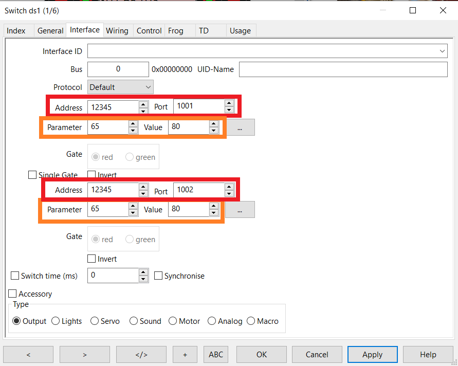
Rocrail setup for double slip switches
The MattzoControllerID must be entered in both “Address” fields.
The MattzoControllerID must be entered as “Address” parameter, and the ports of the two switches are defined in the MLC configuration (1001 and 1002 in this example).
As for standard switches, enter the minimum angle of the switch servo motors into the “Parameter” fields, and the maximum angle into the “Value” fields. Please note that the setting can only be done for a servo pair and per logical switch, not individually for each servo. It is recommended or even required to use identical type of servos within a single logical switch.
ALL OTHER INFORMATION ON THIS PAGE CAN BE NEGLECTED AND HAS NO MEANING!
Switch Sensors
As in reality, Rocrail can deal with switches that have location sensors. Location sensors help to check if a switch is in the correct position.
In this example, a switch has been thrown in Rocrail, but its correct position has not been confirmed:

If a switch has not been confirmed, the switch may still be used by Rocrail to allocate it and to set routes, but it will not start the train to make it travel over the route.
Unfortunately, location sensors would be quite complicated to build for LEGO and compatible switches, but we can at least check if the switch command was received by the MLC and if the controller has converted the command into a servo setting.
The MLC has a feature called “virtual sensors”. These sensors can be defined in the sensor wiring configuration section in the MLC configuration.
#define NUM_SENSORS 2
TSensorConfiguration sensorConfiguration[NUM_SENSORS] =
{
    {
        .pin = -1,
        .pinType = VIRTUAL_SENSOR_PIN_TYPE,
        .remoteMattzoControllerId = -1
    },
    {
        .pin = -1,
        .pinType = VIRTUAL_SENSOR_PIN_TYPE,
        .remoteMattzoControllerId = -1
    }
}
These sensors can then be used in the switch definition:
// SWITCH CONFIGURATION
// Number of switches
#define NUM_SWITCHES 1

TSwitchConfiguration switchConfiguration[NUM_SWITCHES] =
{
    {
        .rocRailPort = 1,
        .servoIndex = 0,
        .servo2Index = -1,
        .servo2Reverse = false,
        .triggerSensors = true,
        .sensorIndex = {0, 1}
    },
}
To make the MLC create sensors events when a switch was thrown, the “triggerSensors” parameter must be set to “true”. The “sensorIndex” array contains the indexes of the two virtual sensors from the sensor wiring configuration (array are zero-based in C++, so the values are 0 and 1).
In order to use the feature in Rocrail, create two sensors in the Rocrail plan. One is for the “straight direction, one for the “thrown” direction. Configure them as if they were physical sensors.
Then navigate to the “Wiring” section of the switch property page. Enter the sensors in the “Sensor turnout” and “Sensor straight” fields as shown below.

Chances are 50/50, that you mixed up the two sensors… just flip them in the dialog above if required.
As soon as the sensors are selected correctly for the switch, a route will not be cleared for a train before the sensors have reported the switch to be in the correct position.
The feature works for all types of switches. For triple switches and double slip switches, four virtual sensors must be created and selected in the switch configuration in Rocrail.
Tipps and Tricks
Flattering servos
Some users have experienced flattering servos in some deployment scenarios. This is usually caused by a “brown-out”, which happens when the power supply for the servos is insufficient and breaks down.
To overcome this problem, you need to make sure that the MattzoSwitchController has enough power. If you power up the controller with USB (4,65V), you should use a charger with 2 Amps minimum. Using higher voltage also helps.
Other countermeasuers include:
- Reduce the length of your cables.
- Use drilled cables.
- Reduce the number of servos attached to the controller.
We are also investigating an idea to change the servo control frequency.
Hi Mattzo,
What kind of servo motors do you use? Mainly TrixBrix I presume?
Cheers,
Raymond
Hi Ray,
indeed I use Trixbrix servo motors. The reason is that I operate almost completely on R104 Trixbrix switches because of their superior geometry, and their larger curve radii. The Trixbrix servo motors fit perfectly on the Trixbrix switches.
Anyway, you may use any servo to operate your switches. Just make sure you calibrate the correct servo angles, and don’t block the servo by turning it into angles that it can not achieve – this will destroy the servo or something else sooner or later.
I am aware that some systems turn the servo, and then go back a couple of degrees after 2 seconds to relieve the servo arm. I believe it’s not necessary when you calibrate your servos carefully, but maybe I will add this option later to the MattzoSwitchControllers.
Could you recommend an alternative to NodeMCU Amica Modul V2 ESP8266 ESP-12F as this can not be purchased anymore
thanks
Hi Andrew,
I think you can use almost any ESP8266 or ESP12 to do the job. Be a bit careful if you use D1 Minis, they do not cope with 9V input voltage. You need a step down module for those controllers.
For the future, I recommend to ask those questions in out new Forum. Navigate to “My Mattzobricks / Forum”.
Cheers,
Mattze
Hey. 🙂
When i use PF M-Motors for switching, can i also use the MLC to control them? I am not afraid of cutting the motor cables if neccesary.
Yes and no. You would need a motor shield and a modification of the firmware. The MLC mini supports servos only that are controlled with a PWM signal. I have used LEGO motors for the first version of the Bascule Bridge, but we went away from that and use servo motors instead, that can be directly connected to both MLC min and MLC mega.
The MTC4PF would be a better hardware platform your project, because it has two integrated motor shields – but, as I said, a firmware modification would be required.
So it would be better to control the switches via servos. You use the TrixBrix ones, right?
Yes, because most of my switches are also from Trixbrix.
Hallo also für Lego habe ich nun folgende werte als gut empfunden: 70 – 85