
The MLC mini is an easy-to-build version of the MattzoLayoutController.
By default, the MLC mini supports 2 switches, 2 light signals and 2 sensors. The configuration can be adapted to support other components like form signals, level crossings or bascule bridges.
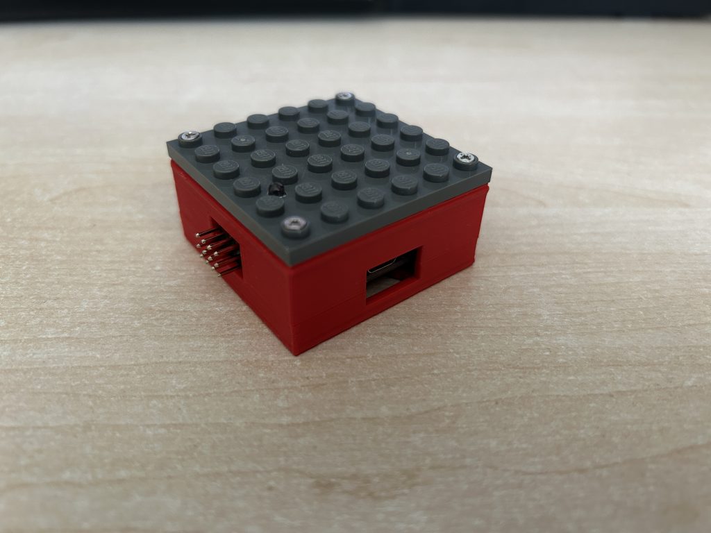
The case has a lateral dimension of only 6×6 studs (4,8 x 4,8 cm) and has a height of 2 bricks and 2 plates (2,56 cm).
Media
I have created a nice little video about how to build the MLC mini. Enjoy!
English version:
German version / deutsche Version:
Building Instructions
First of all: don’t be scared! Building an MLC mini is easy and requires little technical skills and craftmanship only.
Required Material
- 3d printed case, upper and lower part.
- LEGO or compatible plate, 6×6 studs, in your colour of choice.
- ESP8266 strong.
- Connectors 2.54mm, male, triple, angled 90°.
- LEDs, 3mm, in your colour of choice.
- 8 screws, M2x8mm, self-cutting.

Check this page for information where to purchase the material.
Required Tools
- 3D printer to print the case
- Cutter knife to cut the connectors rows
- Soldering iron and solder
- Drilling machine with 2mm and 3mm drills, countersink 45°.
- Screwdriver for the M2 screws
Building Procedure
Follow these steps to build the MLC mini:
1. Print the case
Download the stl files for the upper and lower part of the case and print it with the 3D printer in the colour of your choice.

2. Prepare the LEGO plate.
Drill 2mm holes in the corner studs. This works best of you drill from the bottom of the plate.
Use the countersink to widen up the holes that they can contain the 2mm screws completely. The top part of the screws shoud not be higher than the studs.
Drill a 3mm hole for the status LED.

If you have a problem with hurting LEGO parts: use a Chinese third-party plate or use the controller without the top plate.
3. Cut the connector bar.
The angled connectors come in bars of 40 triple pins. Cut the bar in portions of 4. You need 2 of the resulting 4×3 angled connectors.

4. Solder the angled connectors to the ESP8266.
Insert the connectors into the board:
- Rows D1-D4
- Rows D0, D5, D6, D7
The video shows the precise orientation of the connectors.


Row D8 must remain clear for the status LED.
5. Screw the top LEGO plate on the upper part of the case.
Make sure the hole for the LED is in the right place. The LED will be placed in function pin D8 – the orientation of the plate should look like this:

Screw four of the M2 screws into the corners.

Depending on the 3d print of the case, the screwing might take some force. To make the screwing easier, you can pre-drill the holes with an 1mm drill, or use an electric screwdriver.
6. Install the LED on the ESP8266.
- Plug the LED into the ESP8266, but do not solder it to the controller yet!
- Anode (long pin) goes to pin D8, Cathode (short pin) to GND.
- Put the ESP8266 into the upper case. The LED should now stick in the 3mm hole that you drilled before.
- Adjust the LED as required.
- Solder the LED to the ESP8266.


7. Screw the bottom part of the case to the upper part.

Congratulations! You have just built your first MLC mini!
Firmware
The device requires a specific firmware. Find instructions how to configure and upload the firmware here.
There is a standard configuration for the MLC mini in the MattzoLayoutController firmware. In this default configuration, the mapping of the function pins to hardware components is as follows:
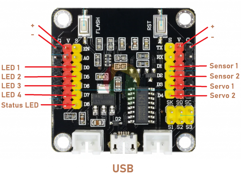
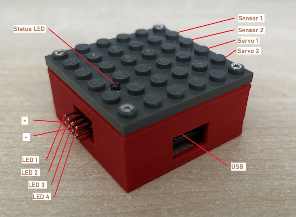
These mnemonic bridges help me to identify the right pins for the components without looking up the specification every time:
- Ground (GND, -) is always on the bottom.
- The side with the status LED is used to connect all other LEDs as well.
- The two servos consume a lot of power, so their pins are closer to the power plug than the sensors pins.
Make sure that you connect the correct components to the controller whenever you power it up. Incorrect wiring may damage the controller.
Other MattzoLayoutControllers
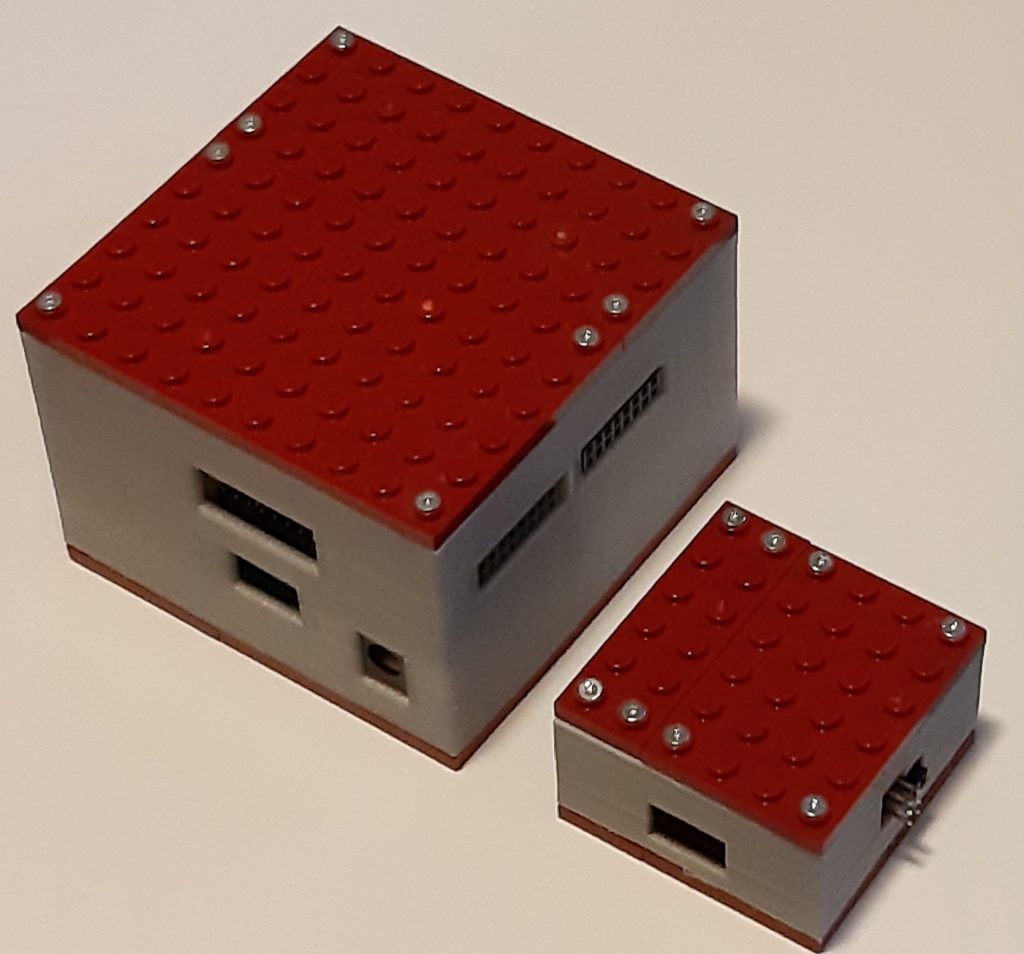
The MLC mini is not alone. It has a big brother, called the MLC mega, which is even more powerful.
Stay informed!
To stay up to date, please check this page regularly for updates and subscribe to our social media channels!
Credentials
The MLC mini was designed by Jona from the Mattzobricks core development team.
The building instructions were compiled by Mattze.
The picture below step 5 can be slightly confusing. The blue 3D-printed case is upside down. You might want to change it to not confuse new users.
True – thank you for your feedback.