
Purpose
MTC4BT acts as a bridge between Rocrail and BLE (Bluetooth Low Energy) devices. The MTC4BT connects to an MQTT broker via WiFi, which in turn connects to Rocrail.
BLE devices connect to the MTC4BT via the Bluetooth Low Energy (BLE) protocol, such as:
- BLE hubs, which control train motors and lights through wires connected to each of their channels,
- BLE remote controls, which are used to control trains and accessories manually.
The following images shows the ecosystem around the MTC4BT:
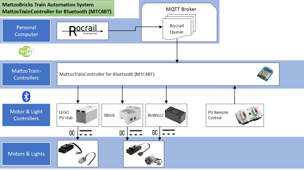
Supported devices
MTC4BT supports the following BLE devices:
- LEGO Powered Up (PU) hub
- SBrick by Sengit
- Buwizz 2.0
- LEGO Powered Up remote control
Up to nine BLE devices can theoretically be connected to the MTC4BT at the same time (though limited in practice to about 5 devices). BLE devices can be combined. This means that you can control a mix of up to nine BLE devices using just one single ESP-32 controller. You can even combine different types of BLE devices in one locomotive if needed, and have an additional LEGO Powered Up remote control connected to drive the train manually or flip a switch.
Use Cases
The two main use cases of the MTC4BT are controlling trains and connect remote controls. The two use cases vary quite strongly, though they can be combined in a single MTC4BT. For this reason, we described the specific functionality and configurations options in separate pages.
Please find all details here:
- MTC4BT as MattzoTrainController
- MTC4BT as MattzoRemoteController
Required Components
- An ESP-32 controller. Check the material page for details and purchase information.
- Some kind of power source. You could use a small USB power pack, or, if deployed on land, a small USB charger can be used alternatively.
- A USB cable to connect the controller to the power source (also required for flashing the firmware, at least for the first time).
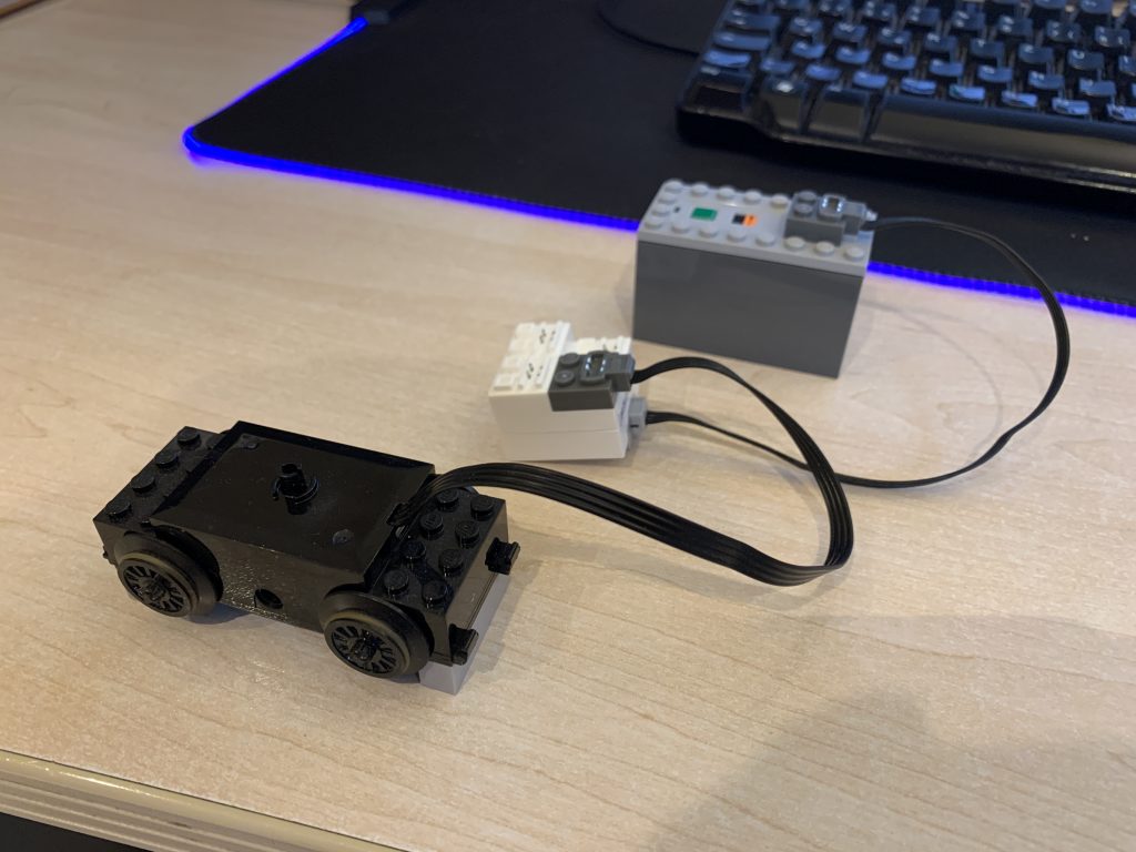
- A device that you would like to connect to the MTC4BT, e.g. a LEGO Powered Up Hub, an SBrick, a Buwizz2 unit or a LEGO Powered Up remote control.
Choosing the right hardware
With firmware release 1.2, our hardware support strategy for the MTC4BT has changed.
Hardware options
We will support the following hardware options:
- A classical ESP32 microcontroller, operated in wireless mode.
- We are presently testing various variants of the ESP32, and will give you advice shortly of what to buy precisely.
- We will very likely promote an ESP32 module with an external Wifi / Bluetooth antenna to guarantee a sufficient range on larger layouts.
- No soldering required.
- This solution has proven stability issues when in high traffic situations and complex layouts, as the RF module in the ESP32 has problems when continuously switching between Bluetooth and Wifi operation. This means, that the controller may crash frequently.
- A classical ESP32 microcontroller, operated in wired mode.
- In this option, the MattzoController connects via Ethernet to the network. This relieves the ESP32 of changing the assignment of the built-in RF module between Wifi and Bluetooth operation constantly.
- We are presently testing various variants of the ESP32, and will give you advice shortly of what to buy precisely. It will likely be an ESP32 with an external Bluetooth antenna to guarantee a sufficient range on larger layouts.
- This option provides you with a perfectly stable controller with a very high rate of reliability.
- A ESP32-S3 microcontroller, operated in wireless mode.
- We have tested the Seeed Xioa ESP32-S3 microcontroller, and it worked great.
- This solution is perfectly stable and reliable.
- The controller has an external Wifi/Bluetooth antenna, which provides a superb range. Can be used on larger layouts without limitations.
- No soldering required.
- No BuWizz2 support yet.
- Presently max. 5 Bluetooth devices per controller.
Purchase information can be found on the material page.
Recommendations
So, which hardware should you buy?
Follow this algorithm:
- Will your controller be deployed stationary (not on a train)?
- Yes:
- Are you using BuWizz2 hubs?
- No:
- Choose option 3 (ESP32-S3)!
- Yes:
- Are you able to do some basic, easy soldering, and do have a free Ethernet port near your layout?
- Yes:
- Choose option 2 (classical ESP32 with Ethernet module).
- No:
- Choose option 1 (classical ESP32) and accept potential stability issues.
- Yes:
- Are you able to do some basic, easy soldering, and do have a free Ethernet port near your layout?
- No:
- Are you using BuWizz2 hubs?
- No (mobile deployment, controller rides on a train):
- Are you using BuWizz2 hubs?
- No:
- Choose option 3 (ESP32-S3)!
- Yes:
- Choose option 1 (classical ESP32) and accept potential stability issues.
- No:
- Are you using BuWizz2 hubs?
- Yes:
Wiring
If you use on of the wireless hardware options, just connect the ESP32 with the USB cable to the power source.
If you use the Ethernet option, then you need to order a PCB, and do some (easy) soldering. We will give you additionally information about building this option shortly.
Prepare your environment
Setup your development environment
We assume you have Visual Studio Code installed with the PlatformIO plug-in. There are numerous tutotials on how to do this, so we won’t get into that here.
There are a couple of things you should get and some other things that are important when setting up your PlatformIO development environment.
Get the source code
The firmware source code is hosted in this github repository:
https://github.com/Mattzobricks/MattzoControllers.git
Check out the firmware to a local directory of your choice.
The source code for the MTC4BT is located in the main folder MattzoControllers. In there is a file named MattzoControllers.code-workspace, which you should open from VS Code (use menu File / Open Workspace from File). This will open the correct workspace in VS Code. Then browse to the subdirectory “MTC4BT”.
Now you need to configure a few things before you can actually configure your controller.
Prepare PlatformIO for the ESP-32 platform
You need to install the ESP-32 platform framework. In VS Code in the left navigation bar go to PlatformIO. Under QUICK ACCESS > PIO Home click Platforms. This will open the PIO Home with the PlatformIO Framework Installer. Go to the Frameworks tab and search for “esp32”. Install the Espressif 32 (espressif32) framework. At the time of writing we are using v3.2.0.
Determine board ID for your ESP-32 board
Then you need to determine the right board ID for your board. Click Boards to open the PlatformIO Board Explorer. In case you use the AZ Develivery ESP32 NodeMCU Module you could search for “az-delivery”. The first hit should be “AZ-Delivery ESP-32 Dev Kit C V4”. Click on the plus-sign to the left of the name. This will expose the board ID you need: az-delivery-devkit-v4. Make a note of it or copy it straight to your clipboard, so you have it for later.
For other boards you might find a different board ID!
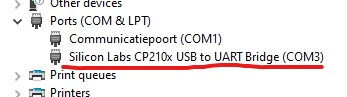
Determine COM port of your development board
First you need to install a driver so your pc can communicate with the ESP-32. You can find the required driver and documentation here:
Then you attach your PC to your pc using a USB cable. Windows will recognize the device and install it. Now you can determine the COM-port your ESP-32 is connected to. For Windows 10/11 you can find this in Device Manager. Search for this device under Ports (COM & LPT):
Configure my_platformio.ini for your controller
Some specifics of your ESP-32 and the connection between the PC to the ESP-32 are stored in the file platformio.ini. This file is under source code control, so changing it is not a good practice. For this reason, platformio.ini references a separate configuration file called my_platformio.ini. This file is not under source code control and can be changed freely at your choice. To get you started, we have created an example platformio.ini file for your convenience. The only thing you have to do is copy my_platformio.example.ini to my_platformio.ini. You then can open and modify it.
Assuming you use the same ESP-32 board we did, you don’t need to change the default board ID. If you use a different board then you must configure platformio.ini for it. You can manually add a new [env:…] section to the platformio.ini file or you can use the PlatformIO UI for this. Under default_envs you can configure the environments PlatformIO should compile when compiling the project. This can be more than one environment, if you want. We stick to the default for now, but if you use a different board and have created a separate [env:…] section for it, you should configure it here.
Last but not least you must configure the COM port of your pc the ESP-32 is attached to. There’s a setting named upload_com_port under the [common] section where you can change it. By default the example platformio.ini is configured to attempt to find your ESP-32 on COM3. Change this to the COM port you found on your pc under Device Manager.
Ethernet option
The ESP32 uses its radio module for both WiFi and Bluetooth over a shared antenna. This requires that the controller switches the antenna continuously between WiFi and Bluetooth. If you operate complex layouts with a lot of trains and components, this can cause problems and instabilities in the MTC4BT.
For this reason, we have integrated a LAN option into the firmware. This option makes it possible to connect the MTC4BT to the MQTT broker via Ethernet. As the controller does not use WiFi, the radio switching problem in the controller is eliminated. With this option, you can expect significant improvements in the area of stability and response times in the high-traffic scenarios mentioned above.
As of firmware V1.2, we are supporting the W5500 Ethernet module.
To wire the W5500 module to the EPS32, the pins must be connected as follows:
| W5500 pin | ESP32 pin |
|---|---|
| RESET | GPIO 26 |
| CS/SS | GPIO 5 |
| MOSI | GPIO 23 |
| MISO | GPIO 19 |
| SCK | GPIO 18 |
| INT | GPIO 25 |
GND and 3V3 must also be connected. Other pins are not connected.
With the LAN option enabled, the controller will try to connect to the network using the W5500 module. If there is no Ethernet cable connected, the controller will fall back to Wifi. Please note that the timeout is quite long. The fallback will only be done during the boot phase of the module. If you disconnect the cable after boot, you need to restart the controller.
OTA will not work if the network connection is established via Ethernet. If you need to update the firmware or configuration via OTA, disconnect the cable and restart the controller, and let it connect to WiFi (that means: wait approximately 1 minute after powering up the MTC4BT until you start the OTA upload). This limitation is caused by the ArduinoOTA library, which is hard wired to Wifi.h. Please note that the IP address is different for WiFi and Ethernet because the network modules use other MAC addresses.
To use the LAN module, you must compile the code with the -DWIRED option. You have to add -DWIRED to the build flags, this is done in my_platformio.ini.
For example:
[common]
; To use w5500 module for wired connections, uncomment the line -DWIRED
additional_build_flags =
 -DWIRED
Controller Configuration
Configuration of the controller has been moved out of the controller source code into two separate JSON configuration files. The first file contains your network configuration, like your WiFi SSID, the WiFi password and the address of your MQTT broker. The second configuration file contains you ESP-32 controller’s configuration. This is where you setup your board’s I/O pins and your locomotives.
Separating the configuration files makes them more flexibel and reusable. It also opens the possibility to change the configuration of the controller, without compiling and uploading a completely new firmware for every small change. VS Code is able to upload just these configuration files (even over the air), which is obviously much faster and more convenient.
At controller boot time, these configuration files are checked and verified, so if something seems wrong you can attach the controller to your PC and look at the serial output or just search through your logs in your syslog host on your network (see the network configuration file) to determine the issue. Make the required changes, upload the config files and try again.
You can find examples of both the network_config.json and controller_config.json in the source code in the data_example folder.
Below you’ll will find some configuration examples, but first we need to determine the MAC address of at least one BLE hub.
Minimal configuration files
Here you’ll find the bare minimum configuration the MTC4BT needs to function.
network_config.json
Below you’ll find the minimal content you need for the network_config.json file. At the very least you need to configure your WiFi access point SSID and password, as well as your MQTT broker’s address.
{
  "wifi": {
    "password": "YOUR_WIFI_PASSWORD",
    "SSID": "YOUR_WIFI_SSID"
  },
  "mqtt": {
    "broker": "YOUR_BROKER_IP"
  }
}
controller_config.json
The controller would actually run with an empty controller controller_config.json file.
{ }
On first glimpse this does not look very useful. But there is indeed a useful application with an empty controller_config.json file: to detect your BLE device MAC addresses! These will be displayed in the serial monitor when you have started the controller.
Detecting the MAC address of BLE devices
To configure the BLE hubs and remotes in the configuration file, you need to know the MAC address of the devices. How do you figure out what they are?
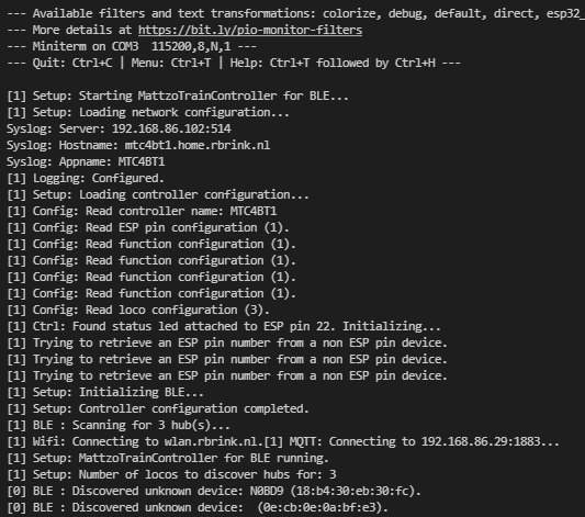
Once you have uploaded the firmware and configuration files (can be as basic as the minimal examples in the previous paragraph), there is a simple option for this built into the controller. You can hook up the MTC4BT to your pc using a USB cable and watch its output on the serial monitor in VS Code:
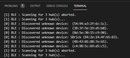
With a little bit of trial and error you can easily find out the MAC addresses of the BLE devices you want to connect.
LEGO Powered Up hints
LEGO Powered Up hubs can be identified easily in most cases, as their MAC address usually starts with “90:84”. There is report about a PU hub that starts with “9c:9a”, so the rule might not be valid in all cases.
Please note that you must resolve the binding of a LEGO Powered Up hub with a PU remote before the hub appears in the list in the serial monitor. You will also not be able to connect to the PU hub if the hub is still connected with a PU remote. To reset the PU hub (and thus resolve the binding to the remote), power on the PU hub, and press the button for about 10 to 15 seconds, until the LED starts blinking or changes color.
It is always a good idea to execute a firmware update on the PU hub before using it with the MTC4BT. To update the firmware, connect the PU hub to the LEGO Powered Up app on your mobile phone. The mobile phone app also displays the MAC address of the hub.
Configuring locomotives and remotes
Now you can start configuring your first locomotive or remote control.
Please refer to these pages to find out about configuring the MTC4BT controller_config.json for:
- locomotives (MTC4BT as MattzoTrainController), and/or
- remote controls (MTC4BT as MattzoRemoteController).
Uploading configuration files to the ESP-32
As mentioned earlier on this page, the controller configuration files (network_config.json and controller_config.json) are not part of the firmware itself. They are stored in a special part of the flash memory of the controller called Serial Peripheral Interface Flash File System or SPIFFS for short. It’s a file system for flash devices and it uses a flat file structure. Conveniently PlatformIO supports it from its UI, but you can also target it from the command line interface.
To upload our controller configuration files to the ESP-32 successfully there are a few prerequisites:
- The workspace must be opened in PlatformIO;
- Both configuration files must be located in the same folder;
- The location of the folder must be configured in your platformio.ini;
Assuming you have the workspace of the project open in PlatformIO and you’ve created both your controller configuration files, we can continue the next step: put them in the right location. This can be any folder really, but we recommend creating a \data folder in the root of the project (the \data folder is ignored by the project completely).
Then you create a subfolder, let’s say MTC4BT1, within that \data folder. This will be the folder that we’re going to be uploading to the controller. If for any reason you want to make some changes to your controller configuration files, you can just create a copy of the folder within the \data folder, say MTC4BT2. This makes it very easy to switch between controller configurations (even while the controller is running!), because you only need to point PlatformIO to the new folder and upload the configuration to the controller. You can even do this over-the-air!
This will trigger a reboot of the controller and your new configuration will be active and running in a matter of seconds.
Now that we have prepared the folder that holds our controller configuration files, we can put the folder path in platformio.ini. One of the first settings in platformio.ini is called data_dir. This setting should point to the folder your put your controller configuration files in. If you followed the example above it’s value should be: $PROJECT_DIR/data/MTC4BT1
Assuming you have your controller connected to your pc and configured the correct COM port in platformio.ini, you can now upload your controller configuration files to the ESP-32. For this PlatformIO has a very handy feature.
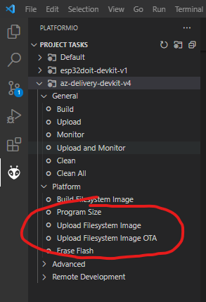
Click on the PlatformIO icon in the left bar in VS Code. The PlatformIO “Project Tasks” pane will open. Click “Upload Filesystem Image” to upload your controller configuration files to the ESP-32 (see image).
If you are an advanced user, and you have integrated your MTC4BTs deeply into some locos or the layouts, you can also opt for “Upload Filesystem Image OTA”. This enables you to upload the firmware and the configuration via WiFi (over-the-air = OTA). Make sure your my_platformio.ini and network_config.json are configured accordingly.
Compiling and uploading firmware to the ESP-32
If you’ve followed the steps above succesfully, compiling and uploading the firmware to the ESP-32 should be pretty straight forward. You need to make sure you:
- opened the workspace file in VS Code (not the repository root folder!);
- connected the ESP-32 to your pc;
- configured the correct COM port in the platformio.ini file;
- configured the correct board in the platformio.ini file;
For the controller to be able to boot after uploading the firmware, you also need to have uploaded a valid network_config.json and controller_config.json. If you boot the controller without configuration files and with invalid ones, the controller will report this in the serial monitor with a message like “Config file is empty”.
Assuming you’ve done all this, you can compile and upload the firmware with a few clicks.
Click on the PlatformIO icon in the left bar in VS Code. The PlatformIO “Project Tasks” pane will open. Click “Upload” to compile and upload the firmware to the ESP-32 (see image). You can also opt for “Upload and Monitor” if you want to automatically open the serial monitor after uploading.
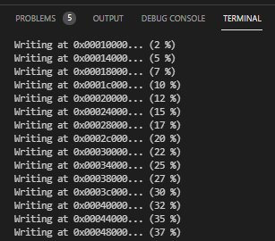
The output will look like this while uploading the firmware:
If you had the serial monitor opened or have opened it manually, you should see the controller boot:
Congratulations if you made it this far! If you have loaded a valid configuration into your controller, you should now be able to control your trains from Rocrail.